Manufacturing method of fabricated floor slab with connecting members
A technology for connecting components and manufacturing methods, which is applied to floors, building components, manufacturing tools, etc. It can solve the problems of limited load-bearing performance improvement, difficulty in meeting the needs of floors, and complicated assembly processes, so as to reduce the amount of cast-in-place and overall transportation And hoisting is convenient, the effect of reducing production costs
- Summary
- Abstract
- Description
- Claims
- Application Information
AI Technical Summary
Problems solved by technology
Method used
Image
Examples
preparation example Construction
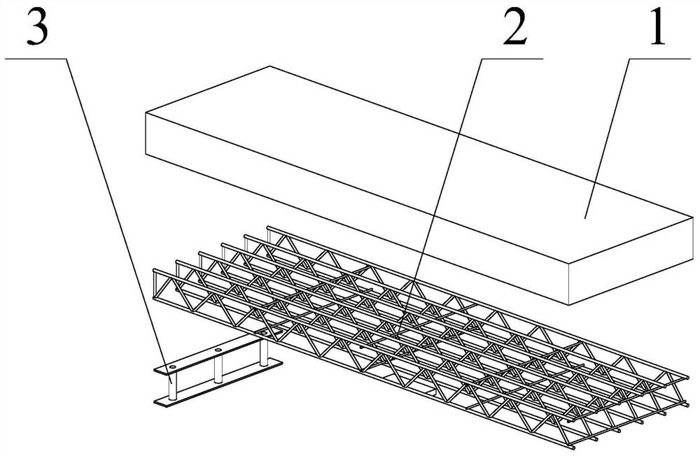
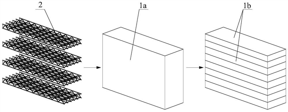
[0052] The core of the preparation method of the present invention lies in step S1 and step S3. Firstly, according to the corresponding building type, the corresponding steel bar trusses 2 are configured, and connecting members 3 are connected at both ends of the steel bar trusses 2 . Then, according to the setting of the cutting equipment used in the cutting link of the subsequent production, the steel bar trusses 2 are stacked and arranged in the concrete mold at intervals. When stacked, the steel bar truss 2 can be fixed and positioned by inserting brazing. Specifically, a drill hole can be provided on the mold, and then the fixing drill is inserted into the mold through the drill hole, and the steel bar truss 2 can be accurately fixed in the mold through the fixing drill. After the mud is poured in, it is only necessary to take out the fixing braze to complete the implantation of the steel bar truss 2 . This production method can effectively realize the accurate implanta...
Embodiment 1
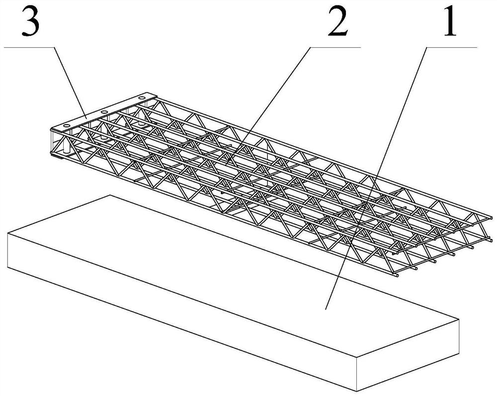
[0066] Such as figure 1 , figure 2 As shown, the prefabricated floor slab of this embodiment includes a load-bearing steel truss 2 and an autoclaved aerated concrete slab 1 , and the steel truss 2 is embedded in the autoclaved aerated concrete slab 1 .
[0067] The present embodiment adopts the following steps to prepare:
[0068] Step S1, prepare steel bar truss 2, firstly prepare a single-piece steel bar truss composed of upper and lower chord main bars 2a and web auxiliary bars 2b, and then use transversely distributed bars 2c to weld a plurality of steel bar trusses to form a three-dimensional steel bar frame structure Truss 2, and finally welding and connecting steel bars at both ends of steel bar truss 2;
[0069] In step S2, the raw materials of the autoclaved aerated concrete floor 1 are fed according to the ratio of raw materials to make concrete mixed mud;
[0070] In step S3, the steel bar trusses 2 prepared in step S1 are fixedly arranged in the concrete mold i...
Embodiment 2
[0077] Such as figure 1 , figure 2 As shown, the prefabricated floor slab of this embodiment includes a load-bearing steel truss 2 and an autoclaved aerated concrete slab 1 , and the steel truss 2 is embedded in the autoclaved aerated concrete slab 1 .
[0078] The present embodiment adopts the following steps to prepare:
[0079] Step S1, prepare the steel bar truss 2, firstly prepare the triangular steel bar truss composed of the upper and lower chord main bars 2a and the web auxiliary bar 2b, and then use the transversely distributed bars 2c to weld a plurality of steel bar trusses to form a three-dimensional steel bar truss structure 2. Finally, weld the bolt sleeves at both ends of the steel truss 2 and fill the holes with foam glue;
[0080] In step S2, the raw materials of the autoclaved aerated concrete floor 1 are fed according to the ratio of raw materials to make concrete mixed mud;
[0081] Step S3, laying a layer of concrete mud on the reinforced truss 2 prepa...
PUM
 Abstract
Description
Claims
Application Information
 - R&D
- Intellectual Property
- Life Sciences
- Materials
- Tech Scout
- Unparalleled Data Quality
- Higher Quality Content
- 60% Fewer Hallucinations
Browse by: Latest US Patents, China's latest patents, Technical Efficacy Thesaurus, Application Domain, Technology Topic, Popular Technical Reports.
© 2025 PatSnap. All rights reserved.Legal|Privacy policy|Modern Slavery Act Transparency Statement|Sitemap|About US| Contact US: help@patsnap.com


