Petrochemical engineering oil-water separation equipment

An oil-water separation and petrochemical technology, applied in water/sewage treatment equipment, liquid separation, separation methods, etc., can solve the problems of clogging of slag separation parts, unsatisfactory effect, affecting oil-water separation effect, etc., and achieve the effect of improving separation effect.

Inactive Publication Date: 2020-12-04
杨老又
View PDF0 Cites 0 Cited by
  • Summary
  • Abstract
  • Description
  • Claims
  • Application Information

AI Technical Summary

Problems solved by technology

[0004] In view of the deficiencies in the prior art, the object of the present invention is to provide a petrochemical oil-water separation equipment to solve the problem that when the petroleum wastewater is processed, the petrochemical wastewater is the wastewater produced after refining petroleum, which makes the petroleum wastewater contain a large amount of Oil suspended matter, during the oil-water separation process of petroleum wastewater, the waste residue in the petroleum is viscous due to the waste oil pollution, which causes the waste residue to stick to the slag separation part when the waste slag is separated, resulting in blockage of the slag separation part , and the size of the slag separation parts is the same, it is impossible to separate the smaller particles contained in the petroleum wastewater, which will affect the oil-water separation effect and lead to the unsatisfactory effect of the petroleum wastewater treatment.

Method used


Image

  • Petrochemical engineering oil-water separation equipment
  • Petrochemical engineering oil-water separation equipment
  • Petrochemical engineering oil-water separation equipment

Examples


Embodiment 1

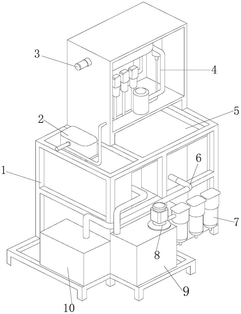
[0032] see figure 1, the present invention provides a technical solution: a petrochemical oil-water separation equipment, its structure includes a frame 1, a dosing device 2, a water inlet pipe 3, a separation tank 4, a slag removal device 5, a delivery pipe 6, and a water purifier 7 , motor 8, water storage tank 9, dirt collection chamber 10, a separation tank 4 is installed on the top of the frame 1, and a water inlet pipe 3 is provided on one side of the separation tank 4, and the water inlet pipe 3 is inserted through the separation tank 4 Above, the bottom of the water inlet pipe 3 is facing the dosing device 2, and the dosing device 2 penetrates into the inside of the separation tank 4 through a connecting pipe, and the separation tank 4 and the dosing device 2 are connected through a connecting pipe. The bottom of the separation tank 4 is provided with a slag removal device 5, the slag removal device 5 communicates with the separation tank 4, the slag removal device 5 ...

Embodiment 2

[0042] see figure 1 , the present invention provides a technical solution: a petrochemical oil-water separation equipment, its structure includes a frame 1, a dosing device 2, a water inlet pipe 3, a separation tank 4, a slag removal device 5, a delivery pipe 6, and a water purifier 7 , motor 8, water storage tank 9, dirt collection chamber 10, a separation tank 4 is installed on the top of the frame 1, and a water inlet pipe 3 is provided on one side of the separation tank 4, and the water inlet pipe 3 is inserted through the separation tank 4 Above, the bottom of the water inlet pipe 3 is facing the dosing device 2, and the dosing device 2 penetrates into the inside of the separation tank 4 through a connecting pipe, and the separation tank 4 and the dosing device 2 are connected through a connecting pipe. The bottom of the separation tank 4 is provided with a slag removal device 5, the slag removal device 5 communicates with the separation tank 4, the slag removal device 5...


PUM


Abstract

The invention discloses petrochemical engineering oil-water separation equipment. The equipment structurally comprises a rack, a chemical feeder, a water inlet pipe, a separation tank, a slag removingdevice, a conveying pipe, a water purifier, a motor, a water storage tank and a sewage collection cavity. After the equipment is improved for use, a connector conveys wastewater onto a blocking screen, large-size particles and impurities in the wastewater are treated through the blocking screen; the wastewater flows to an adsorption sponge felt through the blocking screen; the adsorption sponge felt absorbs residual grease in the wastewater, the residual grease in the wastewater is thoroughly treated, and the treated wastewater is guided to a separation membrane through the flow guide pipe; odor in the wastewater is treated through the separation membrane; and the wastewater is guided into an adhesion plate through material guiding through holes, and the adhesion plate conducts rapid adsorption treatment on small particles in the wastewater, so the particles in the wastewater can be thoroughly separated and removed, and the oil-water separation effect and the slag removal efficiency of the wastewater are improved.

Description

technical field [0001] The invention relates to the field of petroleum machinery, in particular to a petrochemical oil-water separation device. Background technique [0002] Petrochemical industry refers to the processing industry that uses oil and natural gas as raw materials to produce petroleum products and petrochemical products. The process of producing these products is often called petroleum refining, referred to as oil refining. When treating the petroleum wastewater generated by oil refining, it needs Use the slag separation element to isolate the mixture or particles in the wastewater, so that the mixture or particles in the wastewater can be removed. When processing petroleum wastewater, the areas that need improvement: [0003] When processing petroleum wastewater, petrochemical wastewater is the wastewater produced after refining petroleum, which makes the petroleum wastewater contain a large amount of oil suspended matter. During the oil-water separation proces...

Claims


Application Information

Patent Timeline
Patent Type & Authority Applications(China)
IPC IPC(8): C02F9/02C02F1/40
CPCC02F1/001C02F1/281C02F1/40C02F1/44C02F9/00C02F2201/002C02F2201/007C02F2303/04
Inventor 杨老又
Owner 杨老又
Why Eureka
Try Eureka