
Movable water inlet with head positioned by adopting upright post and buoy

A water inlet and movable technology, applied in the field of movable water inlet structure, can solve the problems that the water intake elevation cannot change with the water surface, the water intake point level is not flexible enough, and cannot be adjusted at any time with the water surface, etc., so that the water intake point and the water intake elevation are flexible. , The effect of strong horizontal load capacity and high degree of automation

Pending Publication Date: 2020-12-04
浙江省水利水电勘测设计院有限责任公司
View PDF0 Cites 2 Cited by
  • Summary
  • Abstract
  • Description
  • Claims
  • Application Information

AI Technical Summary

Problems solved by technology

[0005] Although the layered water intake structure can take the water body relatively close to the surface layer of the reservoir, the position of the water inlet is also fixed in height. When there is a large change, it is necessary to switch between the opening and closing of gates at different elevations, and the operation and management are also troublesome
In addition, the location of the water inlet is close to the bank of the reservoir, and the water intake point is not flexible enough on the plane
[0006] There are also projects in which a funnel-like shaft-type water inlet is set in the middle of the reservoir far away from the bank, and the downstream of the water inlet is connected to a water delivery tunnel through the bottom of the reservoir. However, this water inlet also has the disadvantage that the water intake elevation cannot change with the water surface.

Method used


Image

  • Movable water inlet with head positioned by adopting upright post and buoy
  • Movable water inlet with head positioned by adopting upright post and buoy
  • Movable water inlet with head positioned by adopting upright post and buoy

Examples


Embodiment Construction

[0028] The present invention will be described in further detail below in conjunction with the accompanying drawings.

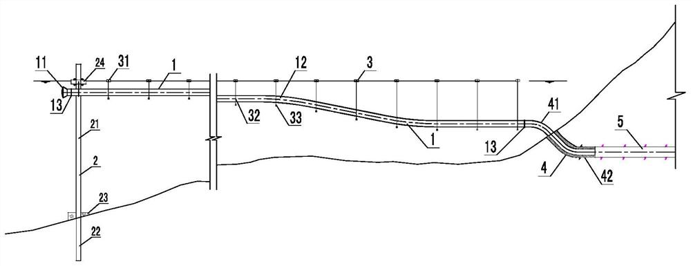
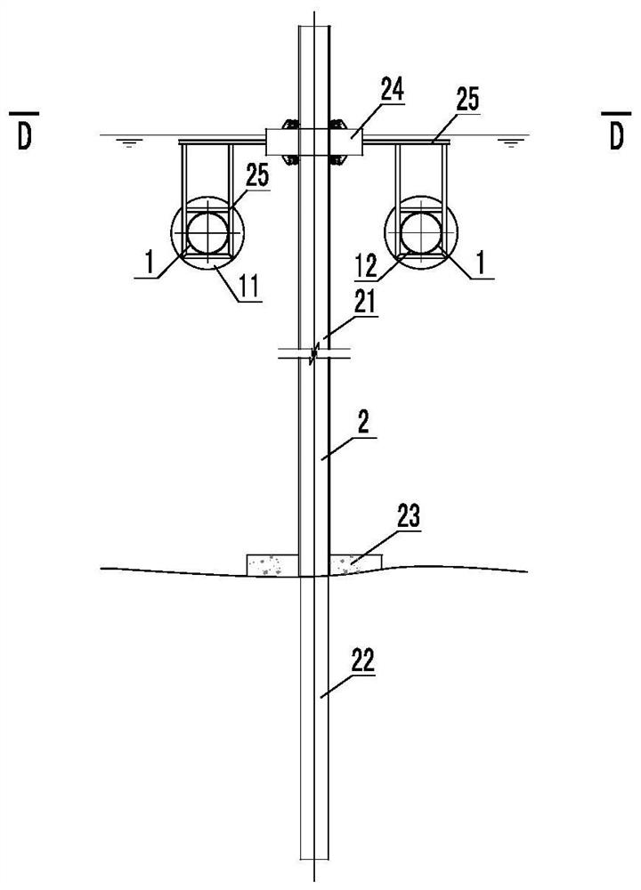
[0029] Such as Figure 1 to Figure 8 As shown, the present invention is a movable water inlet with a head column and a buoy positioned, including a pipeline system 1 , a positioning system 2 , a buoy system 3 and a tunnel sealing section 4 . The pipeline system 1 is the main water delivery structure extending from the water inlet to the reservoir; the positioning system 2 is a positioning structure that fixes the water intake head 11 at the front end of the pipeline system 1 on the plane and elevation; the buoy system 3 is arranged at intervals along the pipeline system 1, mainly The role of the floating pipe 12 of the fixed pipeline system 1 at the design depth below the water surface; the tunnel sealing section 4 is located at the end of the pipeline system 1, which is not only a water retaining structure, but also a fixed pipeline 42 built into the water b...


PUM


Abstract

The invention discloses a movable water inlet with a head positioned by adopting an upright post and a buoy. The movable water inlet comprises a pipeline system, a positioning system, a buoy system and a tunnel plugging section, wherein the pipeline system comprises a water taking head, a floating pipe and a flange joint, and is a main water delivery structure for extending the water inlet to a reservoir for taking water; the positioning system is positioned at the front end of the pipeline system, comprises the upright post, a cast-in-place pile, an upright post expansion foundation, an O-shaped steel buoy, a steel frame and a positioning wheel, and is used for fixing the water taking head at the front end of the pipeline system on a plane and at an elevation; the buoy system comprises the buoy, a steel wire rope and a balancing weight, and is used for fixing the floating pipe at a certain depth below the water surface; and the tunnel plugging section is positioned at the tail end ofthe pipeline system, is a water retaining structure, and is also an overflowing channel for water in the pipeline system to flow to a downstream water delivery tunnel along a built-in fixed pipeline of the tunnel plugging section. The movable water inlet has the advantages of flexible water taking point and water taking elevation, good wind wave resistance of a system structure, high automatic degree along with water level rise and fall, and suitability for water diversion and supply projects with high requirements on water quality.

Description

technical field [0001] The invention relates to a water inlet structure in water conservancy and hydropower projects, in particular to a movable water inlet structure in a water diversion and supply project, the head of which can be far away from the reservoir bank and can take water at a fixed height below the water surface as the water surface fluctuates, and is positioned by a column and a buoy . Background technique [0002] Large-scale reservoirs have large storage capacity and low water fluidity. Due to the influence of water temperature, the water quality often has stratification. The surface water near the water surface has high temperature and high dissolved oxygen content, which is an ideal point for irrigation, water supply and water intake; the deep water near the bottom of the reservoir has a relatively high content of minerals due to the decomposition of organic matter, but the concentration of dissolved oxygen is low. When it is necessary to use the low tempe...

Claims


Application Information

Patent Timeline
Patent Type & Authority Applications(China)
IPC IPC(8): E03B3/04E02B9/00E02B9/02E02D5/34
CPCE02B9/00E02B9/02E02D5/34E03B3/04Y02E10/20
Inventor 赖勇杨茂盛张晴张永进张宇弛区丽雯
Owner 浙江省水利水电勘测设计院有限责任公司
Learn More