
Method and apparatus for ocean energy conversion, storage and transportation to shore-based distribution centers

a technology of ocean energy and method, applied in mechanical equipment, machines/engines, electric generator control, etc., can solve the problems of inability to produce substantial alternate energy fuels or transportation to remote markets without use, devices that are mechanically complex and unsuited to efficiently couple energy, and are restricted to coastal locations with less potential energy

Inactive Publication Date: 2012-06-05
LIGHTFOOT FRED M +3
View PDF19 Cites 18 Cited by
  • Summary
  • Abstract
  • Description
  • Claims
  • Application Information

AI Technical Summary

Benefits of technology

"The patent text describes a method and apparatus for converting ocean energy into useful forms. The technical effects of this patent include the ability to capture and store energy from waves, as well as the ability to use that energy to generate electricity and transport it to shore-based distribution centers. The patent also describes various techniques for adapting and optimizing the performance of the system, including the use of matched filters, ambiguity functions, pulse compression, and signal convolution. The patent text references several other patents and sources of information related to this technology."

Problems solved by technology

These devices tended to be mechanically complex and unsuited to efficiently couple energy over the broad spectrum of ocean wavelengths encountered in practical applications such as in U.S. Pat. Nos. 1,818,066, 1,169,356 and 1,647,025.
For example, Hagan Salter [4], Talya and Yemm designs that are not suitable for producing substantial alternate energy fuels or transportation to remote markets without the use of electrical grids.
These inventions also are restricted to coastal locations with lesser potential energy than the outer banks or open ocean locations.
There are many competing renewable energy applications requiring coastal access like wind turbine farms and tidal current facilities which put practical limits on the number of future hydrokinetic system sites that may be available to meet the nation's needs.
Unfortunately, the storage, transportation, and distribution of hydrogen have been cited as the most significant technological barriers to its widespread implementation.
Any number of proposed renewable energy systems dependent on locations that are remote from their markets have encountered this problem which, if implemented would result in premature obsolescence of existing infrastructure, safety and environmental problems.
What is often not considered by organizations proposing renewable energy is that of the cost of removal and retirement of permanent structures.
Disruption of the coastal fishing industry can occur from “wave energy farms” permanently anchored and operating close to shore that require submerged power cables for interconnection to power grids.
Of course, the environmental costs are more difficult to measure, but exist.
Visual impairment caused by near shore wind farms, intrusion into public recreational facilities, and impairment of waterways by tidal energy systems are detriments to their employment.

Method used


Image

  • Method and apparatus for ocean energy conversion, storage and transportation to shore-based distribution centers
  • Method and apparatus for ocean energy conversion, storage and transportation to shore-based distribution centers
  • Method and apparatus for ocean energy conversion, storage and transportation to shore-based distribution centers

Examples


Embodiment Construction

[0182]A number of alternate means of meeting the functional goals have been presented in the description of this invention. The preferred embodiments for each major apparatus or process are offered as follows:

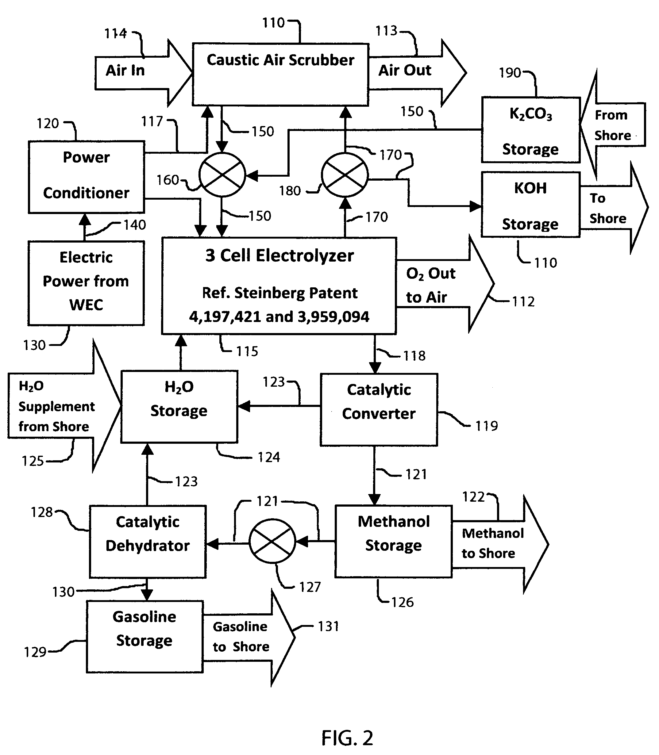
System Energy Storage Medium, FIG. 2

[0183]Molecular hydrogen (H2) is the energy storage medium chosen as the embodiment of choice as opposed to that of electrical energy stored in ultracapacitors or hybrid ultracapacitor / batteries.

[0184]The approach to the production of H2 may be performed by the electrolysis of make-up water from shore facilities such as river water or from municipal sources, or by desalinating sea water. Make-up water from shore facilities is the preferred source of H2.

[0185]Methanol was chosen as the basic medium for storing H2 as opposed to a higher hydrocarbon form.

[0186]Sequestered CO2 recovered from the atmosphere, Potassium Carbonate (K2CO3) is the primary source of CO2 with a secondary source of sequestered CO2 from shore side industrial plants where e...


PUM


Abstract

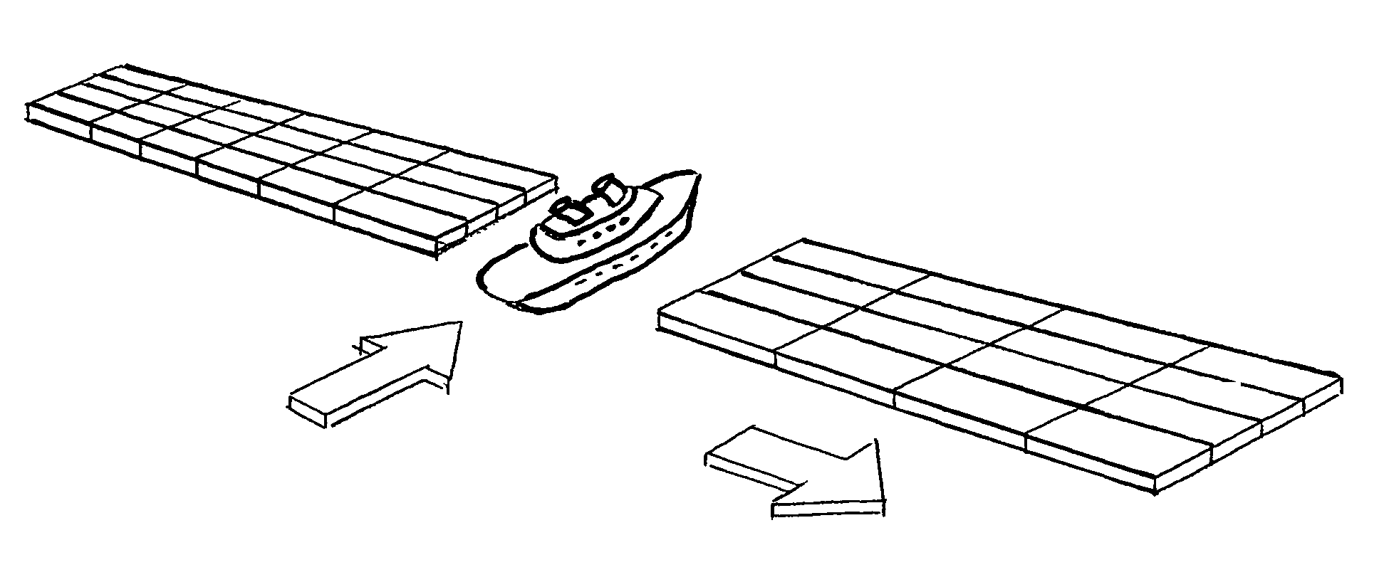
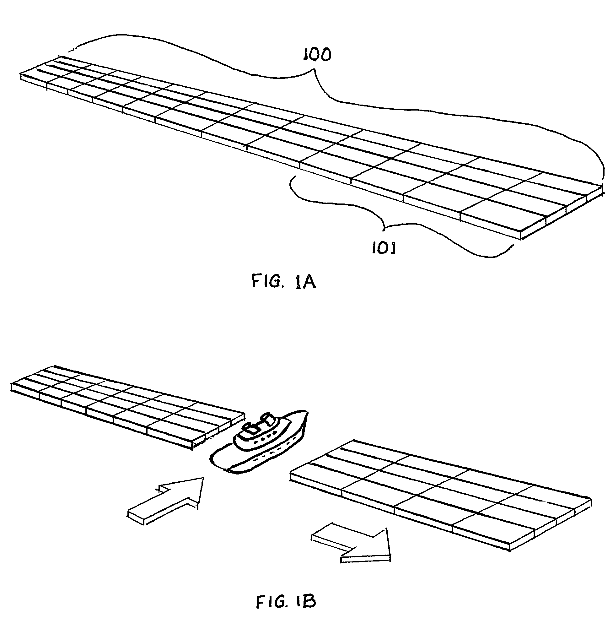
A fleet of vessels attached together longitudinally (rows), and transversely (columns) and operating in unison convert wave energy to electrical energy which is stored in either a chemical or electrical form. The vessels when detached from the fleet provide transportation to coastal or by navigable waterway ports of call for distribution to market centers. Both wind wave and swell wave energy conversion is performed by use of the differential motion between the vessels. Means are provided for the energy conversion systems to adapt to changes in wave direction, wave length, amplitude, and phase. Such vessels are self powered for off shore or inland waterway navigation, either singularly or in multiples, with which to deliver energy to other sea going vessels or to land based ports of call. Two or more of such vessels are capable of using the energy of waves during the delivery process. The fleet can maintain a designated geographical location by dynamic positioning. Alternatively, the fleet may maintain its designated position by moorage of a designated centrally located vessel in the fleet to a permanent anchoring system when operating at appropriate depths.

Description

CROSS REFERENCES TO RELATED APPLICATIONS[0001]This application claims priority from provisional patent application Ser. No. 61 / 269,129 titled Method and apparatus for ocean energy conversion, storage and transportation to shore-based distribution centers filed Jun. 22, 2009, the teaching of which are incorporated herein by referenceREFERENCESA. U.S. Patent Documents[0002]1. U.S. Pat. No. 4,249,084 Villanueva, et al., Scheme for harnessing hydroundulatory power, Feb. 3, 1981.[0003]2. U.S. Pat. No. 4,878,452 Regan, et al., Quick-release mooring apparatus for floating vessels, Nov. 7, 1989.[0004]3. U.S. Pat. No. 6,476,511 Yemm, et al., Floating apparatus and method for extracting power from sea waves, Nov. 5, 2002.[0005]4. U.S. Pat. No. 7,215,036 Gehring, Current power generator, May 8, 2007.[0006]5. U.S. Pat. No. 7,331,174 Welch, Jr., et al., Buoyancy pump power system, Feb. 19, 2008.[0007]6. U.S. Pat. No. 4,077,213 Hagen; Glenn E., Wave driven generator, Mar. 7, 1978.[0008]7. U.S. Pa...

Claims


Application Information

Patent Timeline
Patent Type & Authority Patents(United States)
IPC IPC(8): F03B13/10H02P9/04
CPCF03B13/20F05B2210/16F05B2220/61F05B2260/02F05B2260/406F05B2270/70Y02E10/38Y02E70/10Y02E10/30Y02E60/36
Inventor LIGHTFOOT, FRED M.MILLIGAN, ROBERT EUGENEEADE, TERRY IVANMORCHIN, WILLIAM CARL
Owner LIGHTFOOT FRED M
Learn More