Supercharge Your Innovation With Domain-Expert AI Agents!

tmd device with eddy current damper

An eddy current damper and damper technology, applied in building types, buildings, building components, etc., can solve the problems of low frequency adjustment accuracy, complex TMD overall structure, and troublesome installation.

Active Publication Date: 2021-05-28
中交二航局建筑工程有限公司
View PDF8 Cites 0 Cited by
  • Summary
  • Abstract
  • Description
  • Claims
  • Application Information

AI Technical Summary

Problems solved by technology

[0004] The main purpose of the present invention is to provide a TMD device with an eddy current damper, which solves the problems of complex overall structure, low frequency adjustment accuracy and troublesome installation of the existing TMD

Method used


Image

  • tmd device with eddy current damper
  • tmd device with eddy current damper
  • tmd device with eddy current damper

Examples


Embodiment 1

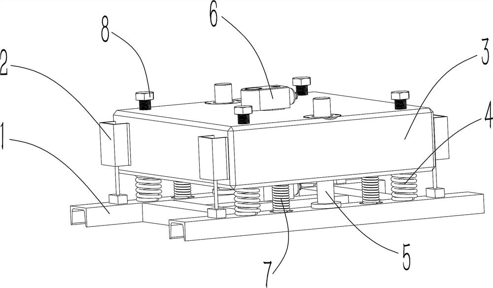
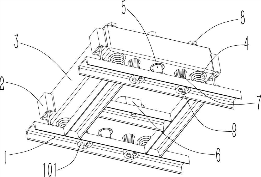
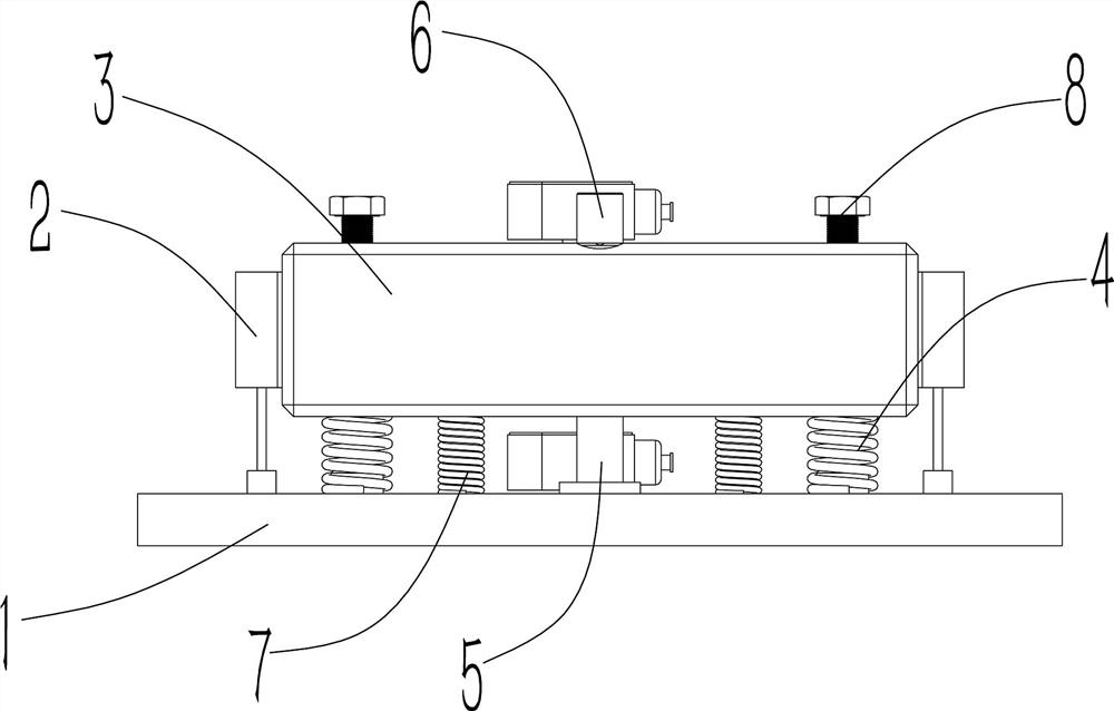
[0033] Such as Figure 1~7 As shown, the TMD device with an eddy current damper includes a support frame 1 fixed under the floor 14, a mass block 3 is provided on the support frame 1, and an adjustment mechanism is provided between the support frame 1 and the mass block 3, so that The height of the center of mass is changed under the action of the adjustment mechanism of the mass block 3, and a plurality of dampers 2 are arranged between the mass block 3 and the support frame 1, so that the mass block 3 vibrates vertically under the influence of the damper 2, and the mass block 3 and the The supporting frame 1 is provided with sensors 6, and the sensor 6 detects the vibration amplitude and frequency of the mass block 3 and the supporting frame 1. With this structure, the TMD device is fixed below the building floor 14 through the supporting frame 1, and the supporting frame 1 The two ends are connected to the beam 15 of the floor 14 by welding or bolting, and the adjustment me...

Embodiment 2

[0047] Such as Figure 8~11 As shown, a TMD device with an eddy current damper, Figure 8 is the graph of the vibration before the TMD device is installed, Figure 9 It is a comparison diagram between the vibration frequency of the floor 14 and the vibration frequency of the TMD device. In the figure, the vibration of the TMD device has a certain time lag due to inertia, so there is a certain time difference with the vibration of the floor 14. At the same time, the vibration amplitude direction of the TMD device is the same as that of the floor 14. The opposite vibration amplitude and direction cancel each other out, so as to suppress the vibration effect. By observing Figure 9 In the comparison diagram of vibration frequency, the function adjustment mechanism adjusts the frequency of the TMD device, so that the TMD device can achieve a better vibration reduction effect. Figure 10 For the vibration curve diagram of the floor 14 after installing the TMD device vibration dam...


PUM


Abstract

The TMD device with an eddy current damper includes a support frame fixed under the floor, a mass block is arranged on the support frame, and an adjustment mechanism is provided between the support frame and the mass block, so that the center of mass can be changed under the action of the mass block adjustment mechanism Height, there are multiple dampers between the mass block and the support frame, so that the mass block oscillates vertically under the influence of the damper, sensors are installed on the mass block and the support frame, and the sensor detects the distance between the mass block and the support frame. Oscillation amplitude and frequency, the structure of the permanent magnet and coil set by the damper, use the principle of electromagnetic Lenz to dissipate energy, improve the effect of suppressing vibration, the adjustment seat and the second spring can adjust the stiffness of the TMD device to adjust the vibration of the TMD device Frequency, usually the stiffness of the TMD device increases, the vibration frequency of the TMD device increases, and the stiffness decreases, the vibration frequency of the TMD device decreases, and the sensor compares the vibration amplitude and frequency of the detection mass and the support frame, thereby acting on the adjustment mechanism. Adjustment, suitable for promotional use.

Description

technical field [0001] The invention relates to the field of civil engineering technology, in particular to a TMD device with an eddy current damper. Background technique [0002] In the field of civil engineering, it is a common measure to use vertical TMD for vibration absorption and vibration control for pedestrian bridges or building structure floors with small vertical natural vibration frequencies. Vertically supported TMDs using compression springs as stiffness elements are very common. The eddy current damper, as a damper with the characteristics of non-contact and high efficiency, is also used in TMD. At present, the general eddy current damping TMD adopts the structure form of the plate type eddy current damping device, and the conductor is generally a copper plate with high conductivity, which is of high quality and high cost, so it is not convenient for engineering promotion. When the TMD is installed on a building, the frequency of the TMD needs to be adjusted...

Claims


Application Information

Patent Timeline
Patent Type & Authority Patents(China)
IPC IPC(8): E04B1/98E04H9/02
CPCE04B1/98E04H9/02E04H9/021
Inventor 张海军刘富发夏受明张宏武周联森余平罗壮赵献计詹银安朱书诚李梁张先辉徐俊彦廖雨薇拜立岗
Owner 中交二航局建筑工程有限公司
Features
  • R&D
  • Intellectual Property
  • Life Sciences
  • Materials
  • Tech Scout
  • Unparalleled Data Quality
  • Higher Quality Content
  • 60% Fewer Hallucinations
Learn More