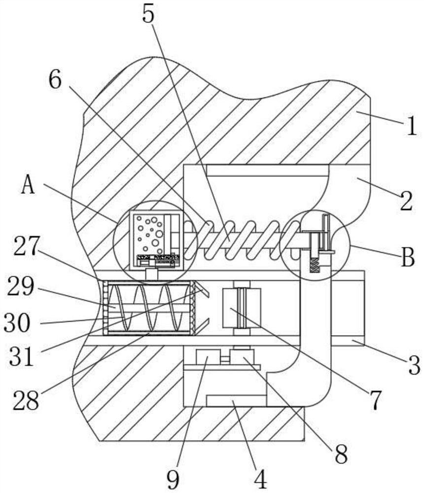
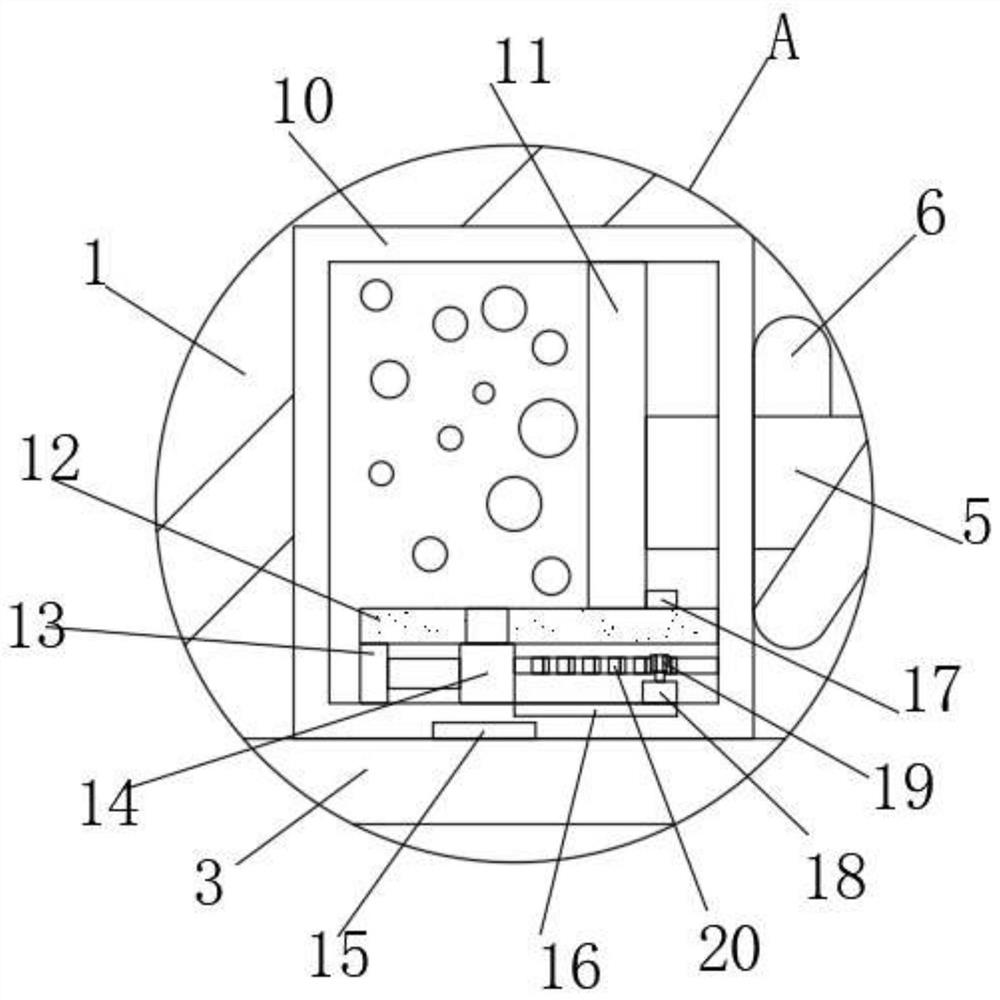
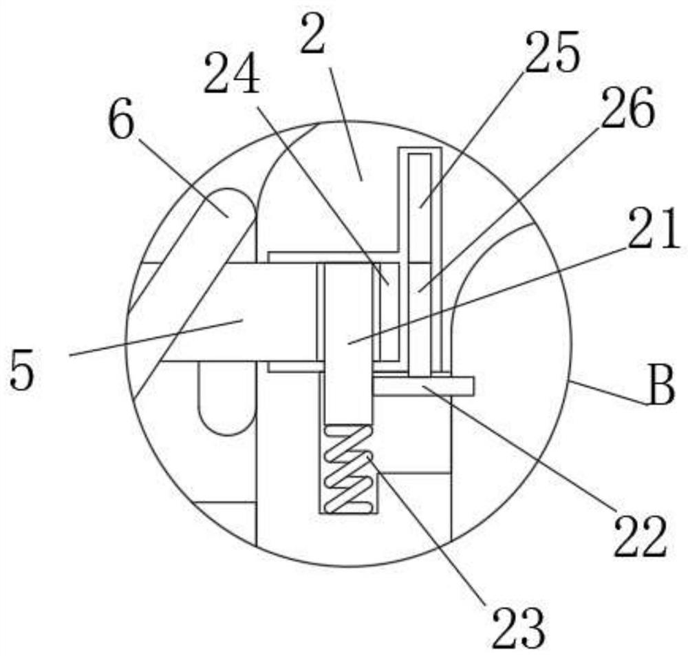
A clamping device for installing the annular side edge of an automobile exhaust pipe cover plate

A technology for automobile exhaust and installation card, which is applied to exhaust devices, power devices, mufflers and other directions, can solve the problems of wasting time and labor, damage to exhaust pipes, environmental pollution, etc., and achieve the effect of saving resources and fully utilizing resources

Active Publication Date: 2021-12-07
青岛益昕实业有限公司
View PDF5 Cites 0 Cited by
  • Summary
  • Abstract
  • Description
  • Claims
  • Application Information

AI Technical Summary

Problems solved by technology

[0003] In the prior art, because the exhaust pipe of the automobile is located on the chassis of the automobile, it is easy to touch when reversing, so that the exhaust pipe is prone to damage. The exhaust pipe of some automobiles is provided with a cover body with anti-collision performance. Sometimes shrinkage will occur. Most of the time, the cover body cannot return to its original position after the collision, so that the cover body is always in the state of shrinking in the rear of the car, which affects the overall appearance of the car. People need professional tools to remove the cover body. Restoring the original position wastes a lot of time and labor in this process. The traditional cover body generally uses nuts and bolts to cooperate with each other to achieve the purpose of fixing the cover body and the rear of the car. Every maintenance adds a lot to the work of the staff. Complexity, when the car is running, the exhaust pipe body will always discharge high-temperature exhaust gas, and this high-temperature exhaust gas will pollute our environment directly in the air, thus accelerating the greenhouse effect

Method used


Image

  • A clamping device for installing the annular side edge of an automobile exhaust pipe cover plate
  • A clamping device for installing the annular side edge of an automobile exhaust pipe cover plate
  • A clamping device for installing the annular side edge of an automobile exhaust pipe cover plate

Examples


Embodiment Construction

[0027] The following will clearly and completely describe the technical solutions in the embodiments of the present invention with reference to the accompanying drawings in the embodiments of the present invention. Obviously, the described embodiments are only some, not all, embodiments of the present invention.

[0028] In describing the present invention, it should be understood that the terms "upper", "lower", "front", "rear", "left", "right", "top", "bottom", "inner", " The orientation or positional relationship indicated by "outside", etc. is based on the orientation or positional relationship shown in the drawings, and is only for the convenience of describing the present invention and simplifying the description, rather than indicating or implying that the referred device or element must have a specific orientation, so as to Specific orientation configurations and operations, therefore, are not to be construed as limitations on the invention.

[0029] refer to Figure ...


PUM


Abstract

The invention discloses a clamping device for installing the annular side edge of the exhaust pipe cover plate of an automobile, which comprises a rear end, a cover plate body and an exhaust pipe body. The rear end is provided with a groove, and the upper and lower sides of the groove are Two guide rails are symmetrically fixedly connected, and the cover plate body is provided with a chute matching the two guide rails, and the cover plate body is slidably connected to the guide rails. A guide rod is slidably connected to the pressure box, and a first spring is sheathed on the guide rod. The design of the invention is reasonable. By setting up a pressure box, filling the pressure box with hydraulic oil and rubber particles, and transferring the heat of the exhaust pipe to the hydraulic oil, the rubber particles are heated and expanded, thereby increasing the air pressure in the pressure box. Therefore, the first piston pushes the cover body back to its original position through the guide rod, which avoids the failure of the cover body to return to its original position after being hit, and the need to find professional staff and tools, thereby wasting time.

Description

technical field [0001] The invention relates to the technical field of auto parts, in particular to a clamping device for installing the annular side edge of an exhaust pipe cover plate of an automobile. Background technique [0002] Automobile exhaust bellows, also known as automobile exhaust pipe hose, is installed in the exhaust pipe between the engine exhaust branch pipe and the muffler, so that the entire exhaust system is flexibly connected, thereby reducing vibration and noise, and is convenient. The function of installing and prolonging the life of the exhaust muffler system is mainly used for light vehicles, miniature vehicles and passenger vehicles. The noise reduction effect is better, and the bellows can be equipped with expansion joints or net sleeves. [0003] In the prior art, because the exhaust pipe of the automobile is located on the chassis of the automobile, it is easy to touch when reversing, so that the exhaust pipe is prone to damage. The exhaust pipe...

Claims


Application Information

Patent Timeline
Patent Type & Authority Patents(China)
IPC IPC(8): F01N13/18F01N13/08F01N5/04F01N5/02F01N3/022F01N3/04F01N3/08B60K13/04
CPCB60K13/04F01N3/022F01N3/04F01N3/08F01N5/02F01N5/04F01N13/08F01N13/1805Y02T10/12
Inventor 金昕杨平李玉恒
Owner 青岛益昕实业有限公司
Why Eureka
Try Eureka