Check patentability & draft patents in minutes with Patsnap Eureka AI!

Voltage stabilizing circuit of contactless alternating-current voltage stabilizer

A technology of AC voltage stabilizer and voltage stabilizing circuit, which is applied to instruments, conversion equipment that can be converted to DC without intermediate conversion, and adjustment of electrical variables. It can solve the problems of back pressure compensation accuracy, circulating current, and low efficiency. It achieves the effects of strong instantaneous overload capability, intact output voltage waveform, and improved dynamic stability

Pending Publication Date: 2020-12-04
上海稳压器厂
View PDF0 Cites 0 Cited by
  • Summary
  • Abstract
  • Description
  • Claims
  • Application Information

AI Technical Summary

Problems solved by technology

[0008] Aiming at the technical problems of circulating current, back pressure and low compensation accuracy in the voltage stabilizing circuit of the traditional voltage stabilizer proposed in the background technology, the present invention designs a new type of AC voltage stabilizer circuit design to solve the problem of circulating current, back pressure and low compensation accuracy. The problem of compensation accuracy, so as to achieve the purpose of high reliability and higher compensation accuracy

Method used


Image

  • Voltage stabilizing circuit of contactless alternating-current voltage stabilizer
  • Voltage stabilizing circuit of contactless alternating-current voltage stabilizer
  • Voltage stabilizing circuit of contactless alternating-current voltage stabilizer

Examples


Embodiment Construction

[0055] The present invention will be further described in detail below in conjunction with the embodiments and the accompanying drawings, but the embodiments of the present invention are not limited thereto.

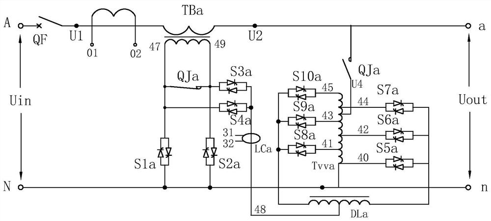
[0056] A non-contact AC voltage regulator circuit, such as image 3 As shown, the circuit connection principle and structure are as follows, including: compensation transformer TBa, voltage regulating transformer Tvva, thyristor S1-S10, three-port inductor DLa and current sensor LCa. Among them, the connection method of the compensation transformer TBa is as follows: one end of the secondary coil of the compensation transformer TBa is connected to the positive pole of the voltage input terminal, and the other end of the secondary coil of the compensation transformer TBa is connected to the positive pole of the voltage output terminal; the primary coil of the compensation transformer TBa passes through several The control function of a thyristor S1-S10, three-port inducto...


PUM


Abstract

The invention relates to the technical field of voltage stabilizers, discloses a voltage stabilizing circuit of a contactless alternating-current voltage stabilizer, and solves the technical problemsthat a voltage stabilizing circuit of a traditional voltage stabilizer has circulating current, back voltage and low compensation precision. Thevoltage stabilizing circuit comprises a compensation transformer TBa, a voltage regulating transformer Tvva, silicon controlled rectifiers S1-S10, a three-port inductor DLa and a current sensor LCa; one end of the silicon controlled rectifier S1 and one end of the silicon controlled rectifier S4 are both electrically connected with one end of a primary coil of the compensation transformer TBa; one end of the silicon controlled rectifier S2 and one endof the silicon controlled rectifier S3 are both electrically connected with the other end of the primary coil of the compensation transformer TBa; the other end of the silicon controlled rectifier S1and the other end of the silicon controlled rectifier S2 are jointly and electrically connected with the negative electrodes of the voltage input end and the voltage output end; and the other end of the silicon controlled rectifier S3 and the other end of the silicon controlled rectifier S4 are jointly and electrically connected with the middle connecting end of the three-port inductor DLa. According to the technical scheme, a novel alternating-current voltage stabilizer circuit design is designed, the problems of circulation, back voltage and compensation precision are solved, and therefore the purposes of high reliability and higher compensation precision are achieved.

Description

technical field [0001] The invention relates to the technical field of voltage stabilizers, more specifically, it relates to a voltage stabilizing circuit of a non-contact AC voltage stabilizer. Background technique [0002] A voltage regulator is a device in electronic engineering that is designed to automatically maintain a constant voltage. [0003] Such as figure 1 as shown, figure 1 The voltage stabilizing circuit is a representative first-generation non-contact voltage stabilizer voltage stabilizing circuit principle in the prior art, which is composed of a voltage regulating transformer TB2 (secondary transformer), a thyristor module S0-10 and a driving circuit. TB2 (auxiliary transformer) is a multi-tap autotransformer, and each tap is controlled by a group of several thyristor switches. Thyristor switches S1~S5 are switching switches for compensation voltage; SCR switches S0, S7, S8, S9 and S10 are switching switches for zero compensation, positive compensation, ...

Claims


Application Information

Patent Timeline
Patent Type & Authority Applications(China)
IPC IPC(8): G05F1/16H02M5/10
CPCG05F1/16H02M5/10
Inventor 包家顺柯金鳌郑奕庆卓泽禄陆雯彬张海江类成民柯蕾
Owner 上海稳压器厂
Features
  • R&D
  • Intellectual Property
  • Life Sciences
  • Materials
  • Tech Scout
  • Unparalleled Data Quality
  • Higher Quality Content
  • 60% Fewer Hallucinations
Learn More