Plate paint spraying and drying device for automobile production
A technology for drying devices and boards, applied in spraying devices, liquid spraying devices, spray booths, etc., can solve the problems of inconvenient operation, consume a lot of time, and use a lot of manual labor, so as to achieve convenient loading and movement, and comprehensive painting. Effect
- Summary
- Abstract
- Description
- Claims
- Application Information
AI Technical Summary
Problems solved by technology
Method used
Image

Examples
Embodiment 1
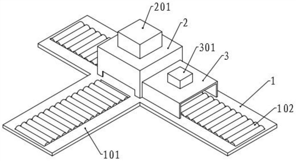
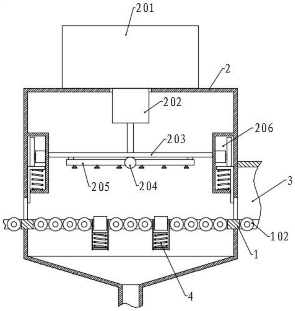
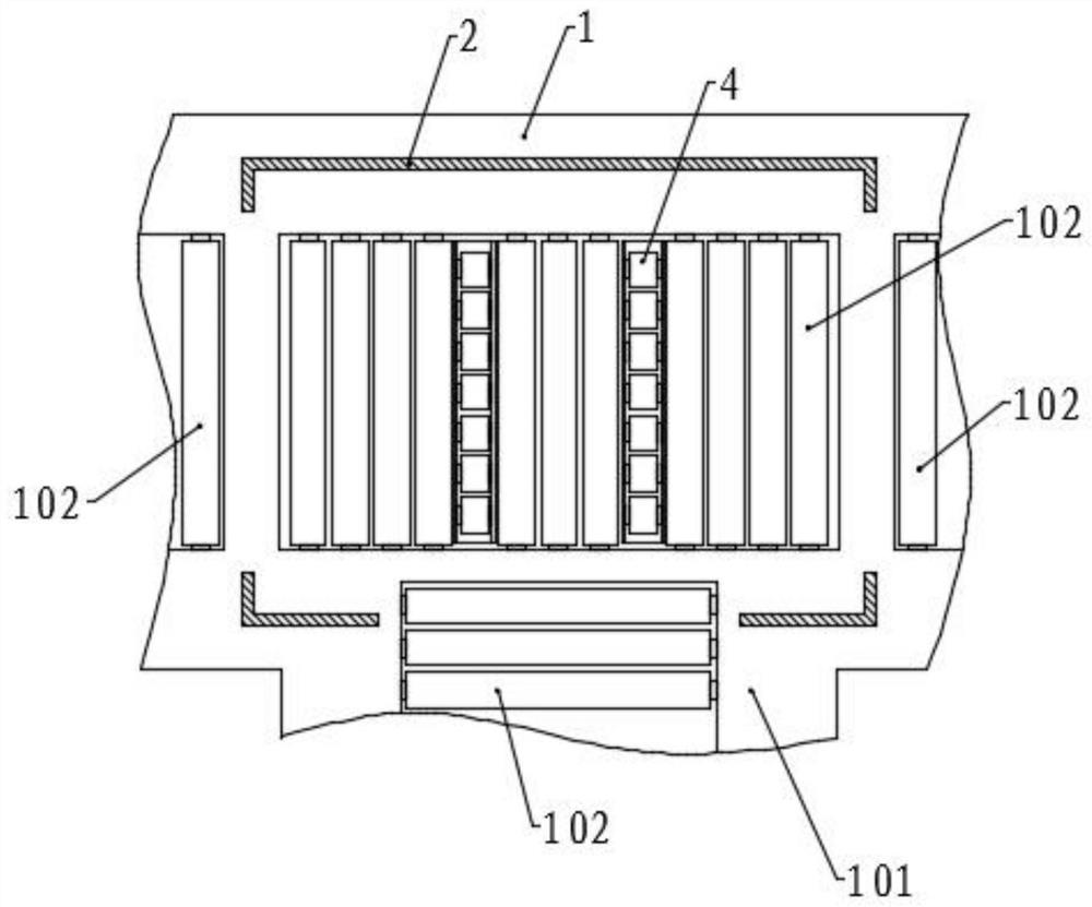
[0054] Please refer to the accompanying drawings, the present invention provides a technical solution: a paint spraying and drying device for panels used in automobile production, including a workbench 1, a return table 101 is vertically fixed in the middle of one side of the workbench 1, and two top surfaces of the workbench 1 The side is symmetrically provided with a first conveying trough, the middle of the top surface is provided with a second conveying trough, the top surface of the return table 101 is provided with a third conveying trough, and the first conveying trough, the second conveying trough and the third conveying trough are all provided with There is a conveying assembly, the conveying assembly includes conveying rollers 102, the two ends of the conveying rollers 102 are rotatably connected with the corresponding conveying trough side walls, and one end of a plurality of conveying rollers 102 is also fixed with a transmission gear 103, and a plurality of transmis...
Embodiment 2
[0067] The structure of this embodiment is basically the same as that of Embodiment 1, except that a transfer mechanism is provided between the side of the workbench 1 close to the drying assembly and the return table 101, and the transfer mechanism includes a fixed assembly 5 and a rotating assembly 6, The fixed assembly 5 is located above the workbench 1 and outside the drying chamber 3 , the rotating assembly 6 is arranged between the workbench 1 and the return table 101 , and one end of the fixed assembly 5 is correspondingly connected to the rotating assembly 6 .
[0068] The fixing assembly 5 includes a first splint 501 and a second splint 502 arranged in parallel, and the inner side of the first splint 501 is vertically fixed with two threaded cylinders 504, and the inner side of the second splint 502 is correspondingly connected with two threaded shafts 503, and the screw thread The inner end of the shaft 503 is screwed into the corresponding threaded barrel 504, the ou...
Embodiment 3
[0073]The structure of this embodiment is basically the same as that of Embodiment 1, except that a collection bucket is fixed in the middle of the bottom surface of the workbench 1, and the length and width of the collection bucket are respectively equal to the length and width of the paint spraying chamber 2, and the bottom surface of the collection bucket A discharge pipe is fixed in the middle, and the discharge pipe is connected with an exhaust fan, and one end of the discharge pipe extends into a treatment box, and a treatment liquid is arranged in the treatment box, so that the air containing the paint liquid in the paint spraying chamber 2 is conveniently discharged, and corresponding treatment is carried out.
PUM
 Abstract
Description
Claims
Application Information
PatSnap Eureka turns technology decisions into work you can execute. Powered by our Innovation Knowledge Graph, it runs expert workflows across engineering, life sciences, materials and intellectual property. Get your review-ready output in minutes.


