Rotary wing vertical take-off and landing hybrid power unmanned aerial vehicle and control method thereof

A vertical take-off and landing, hybrid power technology, applied in the field of aviation aircraft, can solve the problems of low speed cruising altitude, insufficient power utilization of vertical take-off and landing technology, large mixed mass of piston engine and motor, etc.

Active Publication Date: 2020-12-08
NANJING UNIV OF AERONAUTICS & ASTRONAUTICS
View PDF7 Cites 3 Cited by
  • Summary
  • Abstract
  • Description
  • Claims
  • Application Information

AI Technical Summary

Problems solved by technology

[0007] Aiming at the deficiencies of the above-mentioned prior art, the object of the present invention is to provide a rotary wing vertical take-off and landing hybrid unmanned aerial vehicle and its control method to solve the problem of large mass of piston engine and motor mixed in the prior art, and speed cruise. The problem of low height, insufficient power utilization of vertical take-off and landing technology, and poor aerodynamic characteristics of the UAV; the invention adopts the mixed mode of turboprop engine and electric motor to reduce the quality of the whole machine, and improve the power and cruise of the UAV Height and speed, in addition, the present invention has adopted a kind of rotatable wing and tail motor structure, realizes the take-off and landing of UAV by rotating the wing and tail motor when UAV takes off and lands, combines the excellent fixed-wing aircraft The unique cruising power characteristics and the vertical take-off and landing capability of the rotorcraft have greatly improved the drone's battery life, power, survival, maneuvering and other capabilities.

Method used


Image

  • Rotary wing vertical take-off and landing hybrid power unmanned aerial vehicle and control method thereof
  • Rotary wing vertical take-off and landing hybrid power unmanned aerial vehicle and control method thereof
  • Rotary wing vertical take-off and landing hybrid power unmanned aerial vehicle and control method thereof

Examples


Embodiment Construction

[0101] In order to facilitate the understanding of those skilled in the art, the present invention will be further described below in conjunction with the embodiments and accompanying drawings, and the contents mentioned in the embodiments are not intended to limit the present invention.

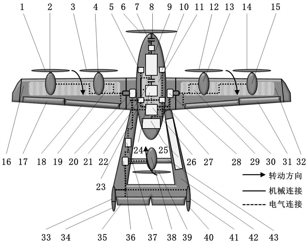
[0102] refer to figure 1 Shown, a kind of rotary wing VTOL hybrid unmanned aerial vehicle of the present invention comprises: fuselage 21, left wing 16 (relative to nose), right wing 32, left aileron 17, right aileron 31 , left flap 18, right flap 30, empennage 42, main propeller 6, left wing motor, left wing propeller, left wing rotary motor 20, right wing motor, right wing propeller, right wing rotary motor 28, empennage motor 38, empennage motor rotary motor 36, Tail motor rotation shaft 43, motor steering converter 37, first vertical stabilizer 33, second vertical stabilizer 41, elevator 35, first rudder 34, second rudder 40, turboprop engine 9, turboprop engine reduction mechanism 7 , ...


PUM


Abstract

The invention discloses a rotary wing vertical take-off and landing hybrid power unmanned aerial vehicle. The unmanned aerial vehicle comprises a vehicle body, a left wing, a right wing, a left aileron, a right aileron, a left flap, a right flap, an empennage, a main propeller, a left wing motor, a left wing propeller, a left wing rotating motor, a right wing motor, a right wing propeller, a rightwing rotating motor, an empennage motor, an empennage motor rotating motor, an empennage motor rotating shaft, a motor steering converter, a vertical stabilizer, an elevator, a rudder, a turboprop engine, a turboprop engine reducing mechanism, a clutch A, a clutch B, an inverter, a power generation / electric all-in-one machine, a storage battery pack, an oil tank, a temperature sensor, a pressuresensor, a state-of-charge estimation module and a control module. When the unmanned aerial vehicle takes off and lands, take-off and landing of the unmanned aerial vehicle are achieved through the rotating wings and the empennage motor, the excellent cruise dynamic characteristics of a fixed-wing aircraft and the vertical take-off and landing capacity of a rotorcraft are combined, and the cruisingability, the power capacity, the survival capacity, the maneuverability and the like of the unmanned aerial vehicle are improved.

Description

technical field [0001] The invention belongs to the technical field of aviation aircraft, and specifically refers to a rotary-wing vertical take-off and landing hybrid unmanned aerial vehicle and a control method thereof. Background technique [0002] With the development of engine and motor technology and the demand for energy saving and emission reduction, gasoline-electric hybrid technology has been successfully applied to automobiles and has been put into the market. However, the integration of hybrid technology in the aviation field is still in its infancy. If the key technology of gasoline-electric hybrid on gasoline-electric hybrid vehicles is used, then the mature gasoline-electric hybrid can be improved while meeting the basic requirements of the flight environment and aircraft design. , it can have a strong impact on the vast aviation field technology. [0003] Nowadays, the fuel consumption of aviation aircraft is huge, which increases the flight cost and reduces...

Claims


Application Information

Patent Timeline
IPC IPC(8): B64D27/02B64D31/00B64C27/22
CPCB64D27/02B64D31/00B64C27/22B64U10/00B64U50/11B64U50/19B64D27/026
Inventor 张自宇王春燕赵万忠宋迎东吴刚曹铭纯孟琦康朱耀鎏于博洋
Owner NANJING UNIV OF AERONAUTICS & ASTRONAUTICS
Why Eureka
Try Eureka