Energy-saving-type cloth cleaning system for spinning

A cleaning system, energy-saving technology, applied in the field of textile production, can solve the problems of insufficient energy utilization, limited spraying range of nozzles, increased power consumption, etc., to achieve the effect of less power, better effect and reduced cost

Active Publication Date: 2020-12-08
HUZHOU YUEBIN INTELLIGENT TECH CO LTD
View PDF5 Cites 5 Cited by
  • Summary
  • Abstract
  • Description
  • Claims
  • Application Information

AI Technical Summary

Problems solved by technology

[0003] 1. Due to the limited spraying range of the nozzles in the existing cloth production and cleaning device, more nozzles should be provided in the device to ensure comprehensive cleaning of the cloth, and the setting of multiple nozzles improves the efficiency of the cleaning process. The cost of making the device;
[0004] 2. In the existing cleaning device for fabric production, since both sides of the fabric need to be cleaned, a motor needs to be used to turn the fabric over. During the whole process, multiple driving devices such as a pump body and an electric motor are required to increase the power. consumption, and will not make full use of energy

Method used


Image

  • Energy-saving-type cloth cleaning system for spinning
  • Energy-saving-type cloth cleaning system for spinning
  • Energy-saving-type cloth cleaning system for spinning

Examples


Embodiment 1

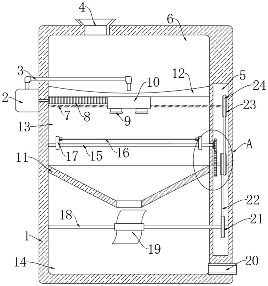
[0025] refer to Figure 1-4 , an energy-saving textile cloth cleaning system, comprising:

[0026] The box body 1 has a hollow cavity inside the box body, and the bottom plate 12 and the conical plate 11 are arranged in the hollow cavity sequentially from top to bottom, and the hollow cavity is divided into a water storage chamber 6 by the bottom plate 12 and the conical plate 11 , processing chamber 13 and water falling chamber 14, water storage chamber 6 is positioned at the top of processing chamber 13, and water falling chamber 14 is positioned at the below of processing chamber 13, and the inner top of water storage chamber 6 is provided with water inlet 4, and one side of water falling chamber 14 is opened There is a water outlet 20, a strip-shaped cavity 5 is provided in one side of the inner wall of the box body 1, and an airtight door 30 is installed on the front side of the box body 1;

[0027] Spraying mechanism, the spraying mechanism comprises the reciprocating s...

Embodiment 2

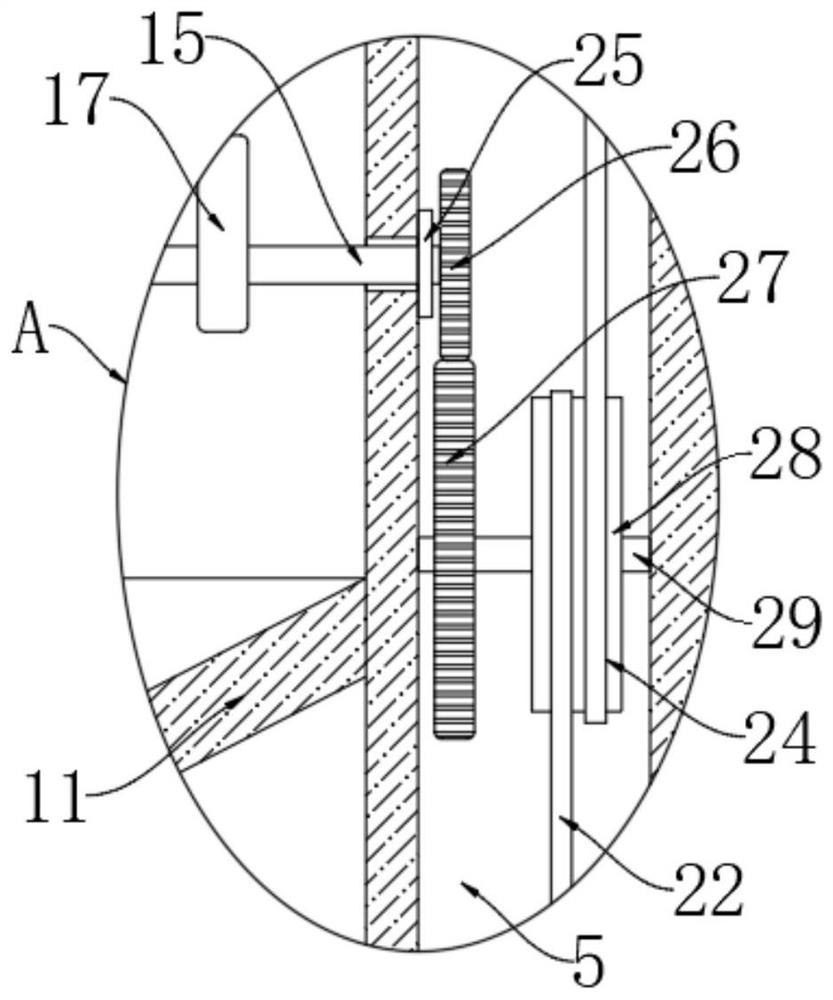
[0036] refer to Figure 5-6 The difference between this embodiment and Embodiment 1 is that the injection structure includes a mounting groove 32 arranged at the lower end of the moving block 10, and the mounting groove 32 is provided with two nozzles 9 which are rotatably connected. The two telescopic airbags 33 are connected, the right side of the moving block 10 is connected with the right inner wall of the processing chamber 13 through the first telescopic airbag 31, and the first telescopic airbag 31 and the second telescopic airbag 33 are communicated through a communication pipe.

[0037] In this embodiment, when the moving block 10 moves left and right, it will drive the first telescopic airbag 31 to stretch and compress. Stretching and compression will drive the second flexible air bag 33 to shrink and expand, that is, when the moving block 10 is moving, the two spray heads 9 are always in a swinging state, so that the spraying range is larger.


PUM


Abstract

The invention discloses an energy-saving-type cloth cleaning system for spinning. The energy-saving-type cloth cleaning system comprises a box body and a spraying mechanism; a hollow cavity is formedin the box body, a bottom plate and a conical plate are sequentially arranged in the hollow cavity from top to bottom, the hollow cavity is divided into a water storage chamber, a treatment chamber and a water falling chamber through the bottom plate and the conical plate, the water storage chamber is located above the treatment chamber, and the water falling chamber is located below the treatmentchamber; a water inlet is formed in the inner top of the water storage chamber, a water outlet is formed in one side of the water falling chamber, a strip-shaped cavity is formed in the inner wall ofone side of the box body, and a sealing door is mounted on the front side of the box body; and the spraying mechanism comprises a reciprocating lead screw horizontally arranged in the treatment chamber, and the two ends of the reciprocating lead screw are rotationally connected with the inner walls of the two sides of the treatment chamber correspondingly. According to the system, only one electric driving device of a pump body is used, electric energy is consumed a little, gravitational potential energy generated when water falls down can be converted into kinetic energy and fully utilized,and the system conforms to the large trend of energy conservation.

Description

technical field [0001] The invention relates to the field of textile production, in particular to an energy-saving textile cloth cleaning system. Background technique [0002] The textile industry is an industrial sector that processes natural fibers and chemical fibers into various yarns, silks, threads, belts, fabrics and their dyeing and finishing products. Cloth is the product of textile production, and after production, the cloth needs to be cleaned before it can be put into use. , with the current cloth cleaning device, there are several problems: [0003] 1. Due to the limited spraying range of the nozzles in the existing cloth production and cleaning device, more nozzles should be provided in the device to ensure comprehensive cleaning of the cloth, and the setting of multiple nozzles improves the efficiency of the cleaning process. The cost of making the device; [0004] 2. In the existing cleaning device for fabric production, since both sides of the fabric need ...

Claims


Application Information

Patent Timeline
IPC IPC(8): D06B1/02D06B23/20D06B15/10
CPCD06B1/02D06B15/10D06B23/20
Inventor 沈超锋
Owner HUZHOU YUEBIN INTELLIGENT TECH CO LTD
Why Eureka
Try Eureka