Engine with compression ratio improving function and engine cylinder group thereof

An engine cylinder and hydraulic cylinder technology, applied in the field of engines and their engine cylinder groups, can solve problems such as difficulty in improving efficiency

Pending Publication Date: 2020-12-08
胡平
View PDF0 Cites 0 Cited by
  • Summary
  • Abstract
  • Description
  • Claims
  • Application Information

AI Technical Summary

Problems solved by technology

[0002] Existing engines have always used adiabatic compression and adiabatic expansion to complete work. Due to the limitations of fuel characteristics and structure, the compression ratio of existing engines has basically reached the limit. It is becoming more and more difficult to improve efficiency by increasing the compression ratio.

Method used


Image

  • Engine with compression ratio improving function and engine cylinder group thereof
  • Engine with compression ratio improving function and engine cylinder group thereof
  • Engine with compression ratio improving function and engine cylinder group thereof

Examples


Embodiment 1

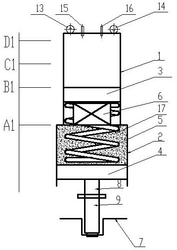
[0041] see figure 1 , this embodiment discloses an engine cylinder group, including a cylinder block 1 and a hydraulic cylinder block 2, the hydraulic cylinder block 2 is located at the lower end of the cylinder block 1, and the head end of the hydraulic cylinder block 2 is connected with the lower end of the cylinder block 1, so that the hydraulic pressure The inner cavity of the cylinder block 2 communicates with the inner cavity of the cylinder block 1, and the hydraulic piston 4 is arranged in the hydraulic cylinder block 2, and the hydraulic piston 4 is in sliding and sealing cooperation with the inner wall of the hydraulic cylinder block 2. An isolation piston 3 is provided, and the isolation piston 3 is in sliding and sealing cooperation with the inner wall of the cylinder body 1. A certain amount of liquid 17 is filled between the isolation piston 3 and the hydraulic piston 4 (the amount of liquid to be filled is determined according to the actual situation, generally n...

Embodiment 2

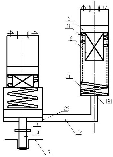
[0057] see Figure 4, this embodiment discloses an engine cylinder group, including a cylinder block 1 and a hydraulic cylinder block 2, an extension part is added to the cylinder block 1, the hydraulic cylinder block 2 is arranged laterally at the lower end side of the cylinder block 1, and the head of the hydraulic cylinder block 2 The end communicates with the side wall of the cylinder block 1, the hydraulic cylinder block 2 is provided with a hydraulic piston 4, and the hydraulic piston 4 is in sliding and sealing cooperation with the inner wall of the hydraulic cylinder block 2, and the cylinder block 1 is provided with an isolation piston 3 , the isolation piston 3 is in sliding and sealing cooperation with the inner wall of the cylinder block 1, the bottom of the cylinder block 1 is sealed, and a certain amount of liquid 17 is filled between the isolation piston 3 and the hydraulic piston 4, (the liquid filled in is determined according to the actual situation Generally...

Embodiment 3

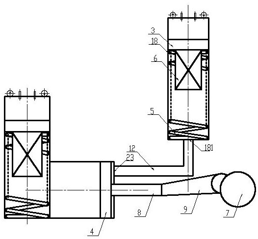
[0068] see figure 1 , the present embodiment discloses an engine with improved compression ratio, comprising at least one engine cylinder group as described in Embodiment 1, the hydraulic cylinder block 2 tail ends of each engine cylinder group are open, and the hydraulic pistons 4 of each engine cylinder group Connect with the crankshaft 7 in the crankshaft 7 case by connecting rod 9. Of course, it is also possible to connect the hydraulic piston 4 to the piston rod 8 and connect the piston rod 8 to the connecting rod 9. The hinged connection between the piston rod 8 and the connecting rod 9 can be the same as the original piston and the connecting rod 9. Certainly, It can be adjusted according to actual needs.


PUM


Abstract

The invention relates to an engine with a compression ratio improving function and an engine cylinder group thereof. The engine cylinder group comprises an air cylinder body and a hydraulic cylinder body, the hydraulic cylinder body is located at the lower end of the air cylinder body, the head end of the hydraulic cylinder body is connected with the lower end of the air cylinder body to enable aninner cavity of the hydraulic cylinder body to be in communication with an inner cavity of the air cylinder body, a hydraulic piston is arranged in the hydraulic cylinder body, the hydraulic piston is in sliding fit with the inner wall of the hydraulic cylinder body, the hydraulic cylinder body is filled with liquid, the hydraulic piston pushes the liquid to enter the air cylinder to form a liquid column to compress air, an isolation piston is arranged in the air cylinder body, the isolation piston is in sliding fit with the inner wall of the air cylinder body, a spring is connected between the isolation piston and the hydraulic piston, and a heat absorber is mounted at the lower part of the isolation piston. According to the engine with the compression ratio improving function and the engine cylinder group thereof, the isolation piston is arranged in the air cylinder to divide the compression process into two stages of near-isothermal compression a1 and adiabatic compression a2, so that the compression work is greatly reduced, the compression end temperature is controlled, the compression end pressure is reduced, and a certain space is provided for improving the compression ratio.

Description

technical field [0001] The invention belongs to the field of engine manufacturing, and in particular relates to an engine with increased compression ratio and an engine cylinder group thereof. Background technique [0002] Existing engines have always used adiabatic compression and adiabatic expansion to complete work. Due to the limitation of fuel characteristics and structure, the compression ratio of existing engines has basically reached the limit, and it is becoming more and more difficult to improve efficiency by increasing the compression ratio. Contents of the invention [0003] The invention provides an engine with increased compression ratio, at least solving one technical problem in the background art, which can reduce the compression work of the engine and greatly increase the compression ratio of the engine. [0004] The present invention is achieved in this way: the present invention discloses a cylinder block of an engine, comprising a cylinder block and a h...

Claims


Application Information

Patent Timeline
IPC IPC(8): F02B71/00
CPCF02B71/00
Inventor 胡平
Owner 胡平
Why Eureka
Try Eureka