Conveying device, method and system

A technology of conveying device and signal processing device, which is applied in the field of heating equipment, cooling equipment or fresh water station, hydraulic system or pneumatic system, which can solve the problem of not setting the active action of valve opening and achieve the effect of improving energy efficiency

Pending Publication Date: 2020-12-08
ROBERT BOSCH GMBH
View PDF1 Cites 0 Cited by
  • Summary
  • Abstract
  • Description
  • Claims
  • Application Information

AI Technical Summary

Problems solved by technology

However, no active action on valve opening is set

Method used


Image

  • Conveying device, method and system
  • Conveying device, method and system
  • Conveying device, method and system

Examples


Embodiment Construction

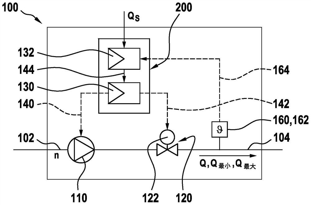
[0024] figure 1 An exemplary delivery device 100 is shown for a fluid not shown such as water or normal air. The delivery device 100 also has a suction side 102 and a pressure side 104 . The conveying device 100 is preferably arranged to be used in a hydraulic system or a pneumatic system, such as a fresh water station or a heating plant, but is not limited thereto. Preferably, the electric pump 110 and the continuously adjustable valve 120 are situated in series between the suction side 102 and the pressure side 104 of the delivery device 100 . The valve 120 preferably has an electric servomotor 122 for continuously adjusting the flow rate of the volume flow Q of the fluid by means of the valve 120 . A volume flow Q of fluid flows through the delivery device 100 from the suction side 102 to the pressure side 104 . It should be noted that in figure 1 The configuration of the delivery device 100 shown in is of an exemplary nature only and should not be considered limiting...


PUM


Abstract

The invention relates to a conveying device (100) for a fluid, in particular water or air, having an electric pump (110) and an adjustable valve (120), the electric pump (110) and the adjustable valve(120) being arranged fluidically in series, and the conveying device (100) having a suction side (102) and a pressure side (104), characterized in that at least one signal processing device (200) isprovided, the signal processing device is designed to sequentially actuate the electric pump (110) and the adjustable valve (120) in order to reduce current consumption. The invention also relates toa method for operating a conveying device (100) for a fluid, in particular water or air, and to a hydraulic or pneumatic system (300) having such a conveying device.

Description

technical field [0001] The invention relates to a conveying device for fluids, in particular water or air, having an electric pump and an adjustable valve, wherein the electric pump and the adjustable valve are fluidically arranged in series, and the conveying device has a pump suction side and pressure side. Furthermore, the invention relates to a method for operating such a delivery device for fluids, in particular water or air, which has an electric pump and an adjustable valve, wherein the electric pump and the adjustable valve are fluidly connected in series and the delivery device has a suction side and a pressure side. The invention also relates to a hydraulic or pneumatic system, in particular a heating plant, a cooling plant or a fresh water station. Background technique [0002] With the advent of regulating circulation pumps in heating or water systems, the throttling switching devices that were common in the past are replaced by pumps and valves due to low ener...

Claims


Application Information

Patent Timeline
IPC IPC(8): F04D15/00F04D27/00
CPCF04D15/0022F04D27/003F04D27/001F04D15/0088F04D15/0005F04B49/225F04B49/065F04D27/0253
Inventor K·埃克哈特
Owner ROBERT BOSCH GMBH
Why Eureka
Try Eureka