Wood pallet drying device

A technology of drying device and wooden pallet, applied in drying, dryer, drying gas arrangement and other directions, can solve the problems of low drying efficiency and the like

Inactive Publication Date: 2020-12-08
重庆龙浩木业有限责任公司
View PDF5 Cites 1 Cited by
  • Summary
  • Abstract
  • Description
  • Claims
  • Application Information

AI Technical Summary

Problems solved by technology

[0004] The present invention intends to provide a wooden tray drying device to solve the problem of low drying efficiency of the existing drying device

Method used


Image

  • Wood pallet drying device
  • Wood pallet drying device
  • Wood pallet drying device

Examples


Embodiment 1

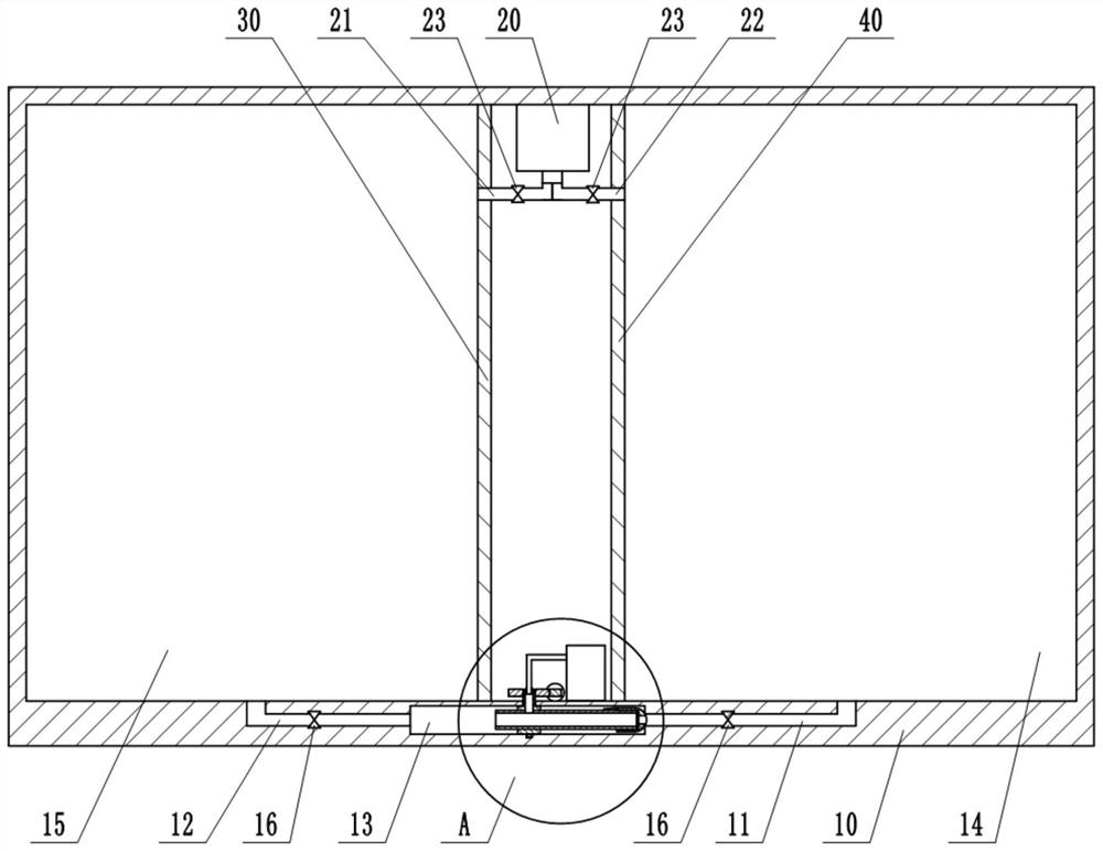
[0024] This embodiment is basically as figure 1 Shown: a wooden pallet drying device, including a drying chamber 10, a vacuum pump 20 and an energy generating mechanism installed in the drying chamber 10. The drying chamber 10 is provided with two mutually independent first drying chambers 15 and second drying chambers 14. In this embodiment, the drying chamber 10 is fixedly equipped with a first partition 30 and a second partition 40, the first partition 30 is surrounded by the left side wall of the drying chamber 10 to form the first drying chamber 15, and the second partition 40 is surrounded by the right side wall of the drying chamber 10 to form the second drying chamber 14. Opening doors are installed on the first dividing plate 30 and the second dividing plate 40, opening the opening doors on the first dividing plate 30 and the second dividing plate 40 can make the first drying chamber 15 communicate with the second drying chamber 14 .

[0025] The vacuum pump 20 is ...

Embodiment 2

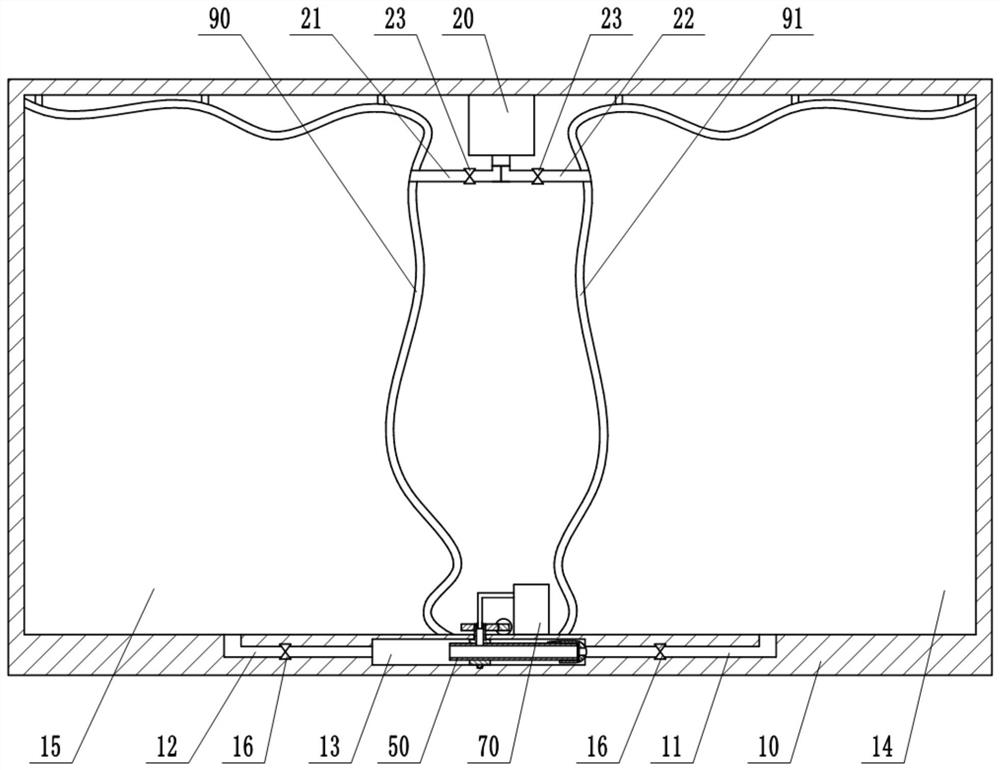
[0030] The difference between this embodiment and Embodiment 1 is that: image 3 As shown, in this implementation, the first partition 30 and the second partition 40 are not provided in the drying chamber 10 , but the first airbag 90 and the second airbag 91 are provided. The first air bag 90 and the left side wall of the drying chamber 10 enclose the first drying chamber 15, and the second air bag 91 and the right side wall of the drying chamber 10 enclose the second drying chamber 14; Both the airbag 90 and the second airbag 91 are provided with sealing bars, which can open and seal the first airbag 90 and the second airbag 91, and the corresponding airbags can be opened by pulling the corresponding sealing bars. The first airbag 90 and the second airbag 91 are both double-layer structures. The interlayers of the first airbag 90 and the second airbag 91 are filled with air, and the thermal conductivity of the air is very low, so that the interlayer has a good heat preservati...


PUM


Abstract

The invention belongs to the technical field of wood drying, and particularly relates to a wood pallet drying device. The wood pallet drying device comprises a drying chamber, a vacuum pump and an energy generation mechanism. A first drying cavity and a second drying cavity are arranged in the drying chamber; an air suction end of the vacuum pump is connected with a first branch pipe and a secondbranch pipe; the first branch pipe communicates with the first drying cavity, and the second branch pipe communicates with the second drying cavity; the energy generation mechanism comprises an air compressor, a vortex tube and a driving unit; a rotating cavity, a first air duct and a second air duct are formed in the bottom of the drying chamber, the first air duct and the second air duct both communicate with the rotating cavity, the first air duct communicates with the first drying cavity, the second air duct communicates with the second drying cavity, and one-way air outlet valves are arranged on the first air duct and the second air duct; the vortex tube is rotationally connected with the interior of the rotating cavity; a nozzle of the vortex tube penetrates through the bottom of thedrying chamber and is located in the drying chamber; and the air compressor communicates with the nozzle of the vortex tube. When the wood pallet drying device is used for drying a wood pallet, waterin the wood pallet is rapidly dissipated, so that the drying efficiency is high, the effect is good, and consumed time is short.

Description

technical field [0001] The invention belongs to the technical field of wood drying, and in particular relates to a wood pallet drying device. Background technique [0002] Pallet refers to a horizontal platform device for loading, stacking, handling and transportation of goods and products placed as a unit load. Wooden pallets are widely used because of their low manufacturing cost, light weight, and ease of processing and manufacturing. Wooden pallets are made of spliced ​​wooden strips and blocks. In order to ensure the quality of wooden pallets and prolong their service life, the moisture (moisture content) in wooden pallets must be reduced to a certain level, which requires drying treatment. [0003] Existing drying operations for wooden pallets generally use a drying device. The existing drying device is generally equipped with a heating mechanism and an air circulation mechanism. The wooden tray is placed in the drying device. By starting the heating mechanism and the...

Claims


Application Information

Patent Timeline
Patent Type & Authority Applications(China)
IPC IPC(8): F26B9/06F26B5/04F26B21/00F26B25/06F26B25/22
CPCF26B5/04F26B9/06F26B21/001F26B21/004F26B25/06F26B25/22
Inventor 胡征碧
Owner 重庆龙浩木业有限责任公司
Why Eureka
Try Eureka