
Metal-halide lamp

A metal halide lamp and halide technology, applied in discharge lamps, gas discharge lamps, parts of gas discharge lamps, etc., can solve problems such as blackening of discharge tube walls, end of lamp life, and discharge tube corrosion, etc. The effect of black reduction

Inactive Publication Date: 2003-09-03
KONINKLIJKE PHILIPS ELECTRONICS NV
View PDF2 Cites 0 Cited by
  • Summary
  • Abstract
  • Description
  • Claims
  • Application Information

AI Technical Summary

Problems solved by technology

[0006] The known lamp has the disadvantage that parts of the discharge vessel, especially the walls, are corroded under the influence of the rare earth metals present during lamp operation
This eventually leads to the premature end of the life of the lamp
A further disadvantage of the known lamps is that also due to the relatively small size of the discharge vessel, the W evaporated from the electrodes deposits on the walls and the blackening of the walls of the discharge vessel occurs relatively quickly.

Method used


Image

  • Metal-halide lamp
  • Metal-halide lamp

Examples


Embodiment Construction

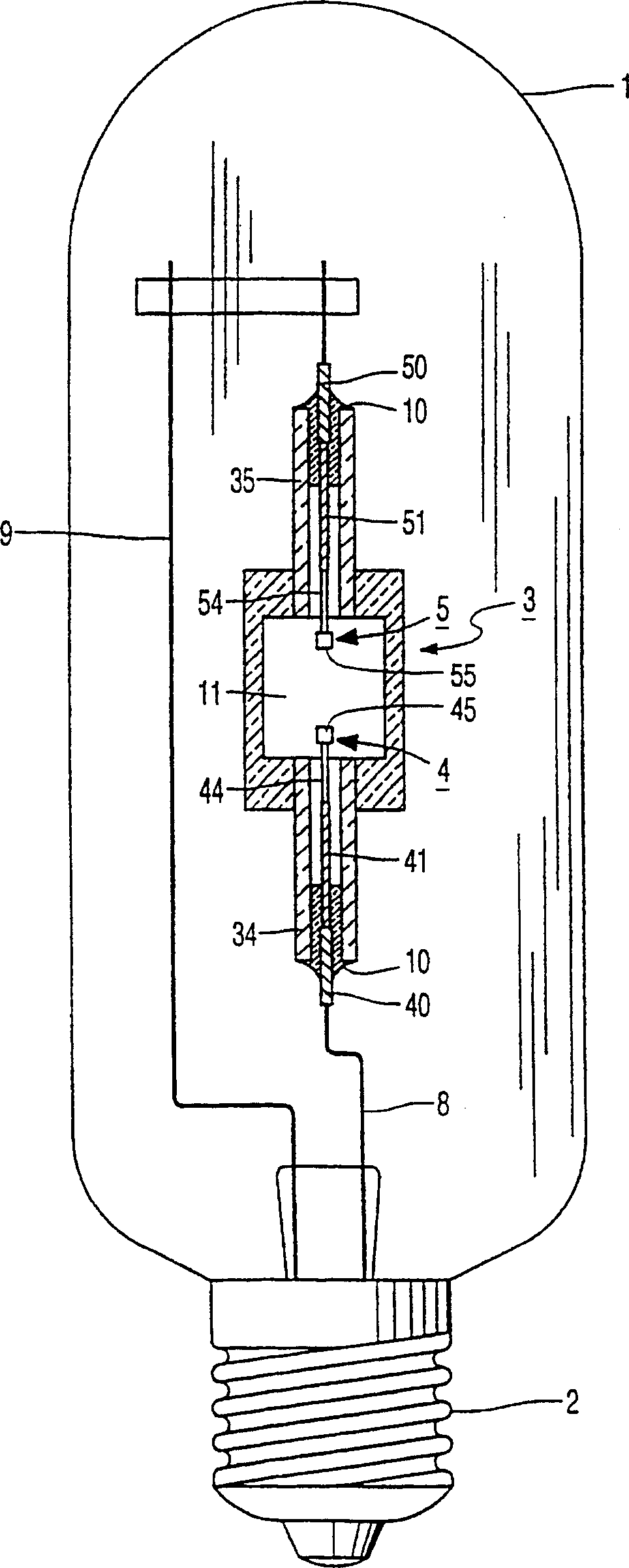
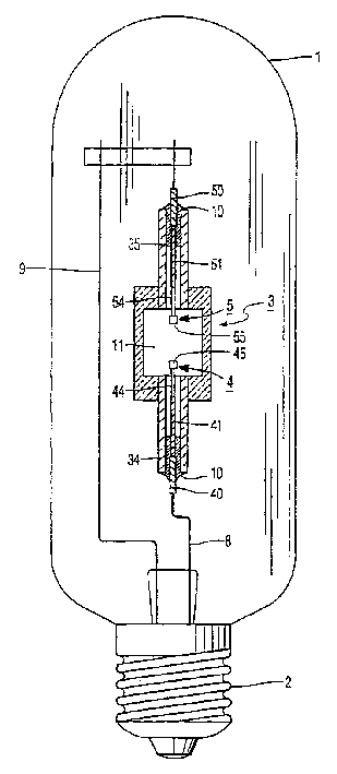
[0014] attached figure 1 A metal halide lamp is shown with the discharge vessel in section, but not to scale, with ceramic walls enclosing a discharge space 11 containing an ionizable filling, which in this case contains not only Hg but also Na and Tl halide. The packing also includes an oxygen distributor comprising CaO, eg in the form of a CaO-impregnated ceramic support. The two electrodes 4, 5 in the figure have electrode rods 44, 54 and top ends 45, 55, both of which are composed of W, and are arranged in the discharge tube. The discharge tube is closed on one side by ceramic protruding plugs 34, 35 on the electrodes 4, 5 arranged in the discharge tube, and the protruding plugs are respectively closely surrounding the lead wires 40, 41, 50, 51 according to a certain gap, and are close to the end of the discharge tube A fused ceramic joint 10 is connected thereto in an airtight manner. The structure of the discharge vessel itself is known, for example from EP-0 587 238 ...


PUM


Abstract

The invention relates to a metal-halide lamp comprising a discharge vessel with a ceramic wall, the discharge vessel enclosing a discharge space which contains an ionizable filling which filling contains a quantity of halide of Na and T1 in addition to Hg. According to the invention, the ionizable filling also contains Ca and is free from rare-earth halides, and further, the discharge vessel contains an oxygen dispenser.

Description

technical field [0001] The invention relates to a metal halide lamp comprising a discharge vessel with ceramic walls. Background technique [0002] A lamp of the type mentioned at the outset is known from EP-A-0215524 (PHN 11.485). The lamp includes tungsten electrodes. Combining high luminous flux with excellent color characteristics (especially general color reproduction general color R a ≥ 0 and a color temperature Tc between 2600 and 4000K) are very suitable as light sources, for example for interior lighting. The feeling of using this lamp is good, and good color reproduction can be obtained when using Na halide as the filling component of the lamp. When this lamp is working, there is a strong expansion and inversion of Na radiation in the Na-D line. This requires a high cold spot temperature T in the discharge tube of at least 1170K (900°C) kp . When the Na-D line is inverted and expanded, two maxima with mutual separation of Δλ appear in the spectrum. [0003] f...

Claims


Application Information

Patent Timeline
Patent Type & Authority Patents(China)
IPC IPC(8): H01J61/12H01J61/24H01J61/28H01J61/82
CPCH01J61/24H01J61/125H01J61/827H01J61/28
Inventor J·L·G·苏伊克M·C·拉尔斯
Owner KONINKLIJKE PHILIPS ELECTRONICS NV
Learn More