A method for realizing maximum power point tracking of optical fiber energy transmission

A technology of maximum power point and optical fiber, which is applied in the direction of optical fiber transmission, optical transmission system, transmission system, etc., can solve the problems of energy transmission optical fiber characteristic change, receiving end photovoltaic effect conversion efficiency and other problems, and achieve power stability and light energy conversion rate High, avoid damage effect

Active Publication Date: 2022-01-14
西安电子科技大学芜湖研究院
View PDF4 Cites 0 Cited by
  • Summary
  • Abstract
  • Description
  • Claims
  • Application Information

AI Technical Summary

Problems solved by technology

The medium used in optical fiber energy transmission is generally a specially treated energy transmission fiber with large core diameter, low loss, and high power tolerance, although this material shows higher energy transfer than traditional optical fibers in the energy transmission process. Efficiency and ability to resist external electromagnetic interference. However, due to the fact that in actual use, as the incident light power continues to increase, the characteristics of the energy-transmitting optical fiber will change during long-term work, and the conversion efficiency of the photovoltaic effect at the receiving end will also be affected. influences

Method used


Image

  • A method for realizing maximum power point tracking of optical fiber energy transmission

Examples


Embodiment Construction

[0015] The present invention will be further described through specific examples below, but it should be noted that these embodiments are not limitations of the present invention, and those of ordinary skill in the art can make functions, methods, or structural equivalent transformations or modifications based on these embodiments. Substitutions are all included within the protection scope of the present invention.

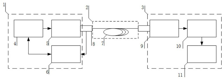
[0016] figure 1 It is a system structural block diagram of the maximum power point tracking scheme based on optical fiber energy transmission in the present invention. The system includes three parts: a sending end 1 , an energy transmission optical fiber link 2 , and a receiving end 3 .

[0017] The sending end 1 includes an FPGA programmable control module 4 , a laser emitting module 5 , and a fiber optic detector 6 . Among them, the FPGA programmable control module 4 is the control core of the transmitting end 1. By continuously collecting the measurement dat...


PUM

PropertyMeasurementUnit
conversion efficiencyaaaaaaaaaa

Abstract

The present invention relates to the technical field of optical fiber energy transmission, a method for tracking the maximum power point of optical fiber energy transmission, comprising a transmitting end 1, an energy transmitting optical fiber link 2, and a receiving end 3, wherein the transmitting end 1 includes an FPGA programmable control module 4, a laser Transmitting module 5, optical fiber detector 6, energy transmission optical fiber link 2 is optical fiber 7, receiving end 3 includes photovoltaic cell 9, photoelectric detection circuit module 10, load transient response circuit module 11, FPGA programmable control module 4 detects laser emission Whether the laser emitted by the module 5 satisfies the set frequency and power, if not, adjust it, the electricity emitted by the photovoltaic cell 9 is detected by the photoelectric detection circuit module 10 and then connected to the load transient response circuit module 11, by adjusting the load transient response The energy storage device connected in parallel with the load in the circuit module 11 switches between the constant voltage output mode and the constant current output mode, so that the photovoltaic cell 9 is always at the maximum power output.

Description

technical field [0001] The invention relates to the technical field of optical fiber energy transmission, in particular to a method for realizing maximum power point tracking during the use of optical fiber energy transmission. Background technique [0002] As an optical waveguide medium, optical fiber has been used as an energy transmission medium in many scenarios in addition to its original large-capacity information transmission capability, which is optical fiber energy transmission. The medium used in optical fiber energy transmission is generally a specially treated energy transmission fiber with large core diameter, low loss, and high power tolerance, although this material shows higher energy transfer than traditional optical fibers in the energy transmission process. Efficiency and ability to resist external electromagnetic interference. However, due to the fact that in actual use, as the incident light power continues to increase, the characteristics of the energy-...

Claims


Application Information

Patent Timeline
Patent Type & Authority Patents(China)
IPC IPC(8): H04B10/80H04B10/50H04B10/564H04B10/60H04B10/25
CPCH04B10/806H04B10/503H04B10/564H04B10/60
Inventor 蔡觉平李天红温凯林岳鹏吴勇王东
Owner 西安电子科技大学芜湖研究院
Why Eureka
Try Eureka