High-temperature constant-temperature pulse-jet ceramic filter pipe type dust removal device integrating high-temperature phase-change heat storage and high-temperature filtration

A high-temperature phase change and pulse injection technology, which is applied in the field of heat storage technology and ceramic high-temperature dust removal, can solve the impact of converter steelmaking and electric furnace steelmaking production, daily maintenance, heavy maintenance workload, and the alternating thermal stress of ceramic filter tubes and other problems, to achieve the effect of reducing the workload of equipment maintenance and repair, saving water, electricity and environmental protection, and prolonging the effect of stability and reliability

Pending Publication Date: 2020-12-11
北京清皓源技术有限公司 +1
View PDF0 Cites 3 Cited by
  • Summary
  • Abstract
  • Description
  • Claims
  • Application Information

AI Technical Summary

Problems solved by technology

[0005] However, for the characteristics of production processes such as converter steelmaking and electric furnace steelmaking, that is, oxygen blowing smelting is not continuous. It is always in the working state of heating and cooling alternate cycles, resulting in a large alternating thermal stress on the ceramic filter tube of the high-temperature flue gas pulse injection ceramic filter tube type dust collector
Under the action of alternating thermal stress, the ceramic filter tube of the high-temperature flue gas pulse injection ceramic filter tube dust removal device has a short service life, and the daily maintenance and repair work is heavy. To a certain extent, it also affects the converter steelmaking and electric furnace steelmaking. big impact on production

Method used


Image

  • High-temperature constant-temperature pulse-jet ceramic filter pipe type dust removal device integrating high-temperature phase-change heat storage and high-temperature filtration

Examples


Embodiment Construction

[0031] In order to make the purpose, technical solution and advantages of the present application clearer, the technical solution of the present application will be clearly and completely described below in conjunction with specific embodiments of the present application and corresponding drawings. Apparently, the described embodiments are only some of the embodiments of the present application, rather than all the embodiments. Based on the embodiments in this application, all other embodiments obtained by persons of ordinary skill in the art without making creative efforts belong to the scope of protection of this application.

[0032] The technical solutions provided by various embodiments of the present application will be described in detail below in conjunction with the accompanying drawings.

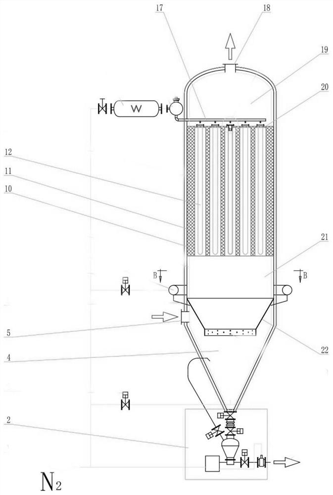
[0033]Such as figure 1 As shown, the high-temperature constant temperature pulse-jet ceramic filter tube type dust removal device according to the present invention includes a cir...


PUM

PropertyMeasurementUnit
mechanical strengthaaaaaaaaaa
porosityaaaaaaaaaa

Abstract

The invention relates to the technical field of heat storage and ceramic high-temperature dust removal, in particular to a high-temperature constant-temperature pulse-jet ceramic filter pipe type dustremoval device integrating high-temperature phase-change heat storage and high-temperature filtration. The device comprises a shell and an ash bucket. The shell comprises an upper box body and a middle box body, A clean high-temperature flue gas outlet is formed in the upper box body, a dusty high-temperature flue gas inlet is formed in the middle box body or the ash bucket, a dusty flue gas primary cyclone separation / airflow equipartition device is arranged at the dusty high-temperature flue gas inlet, and a honeycomb-shaped high-temperature phase change heat storage device is arranged in the middle box body. The high-temperature phase change heat storage device is provided with cavities, and a ceramic filter pipe is arranged in each cavity. Compared with other dust removal and purification modes, the high-temperature pulse-jet ceramic filter pipe type dust removal device with the built-in high-temperature phase change heat accumulator is high and stable in efficiency, can guaranteestable recovery of clean dry gas and quality of discharged flue gas, can avoid a micro-explosion phenomenon frequently generated by electric dust removal sparks, and enables the system to operate moresafely.

Description

technical field [0001] The invention relates to the technical fields of heat storage technology and high-temperature ceramic dust removal, in particular to a high-temperature constant-temperature pulse-jet ceramic filter tube-type dust removal device integrating high-temperature phase change heat storage and high-temperature filtration. Background technique [0002] High-temperature flue gas purification has become an important technical research topic for materials, metallurgy, chemical industry, electric power and other industries to achieve "energy saving and emission reduction". Many industrial flue gases are high-temperature flue gases, such as smelting, incineration, thermal power generation, coal-fired boilers, industrial furnaces, waste heat recovery and utilization, etc. At present, the traditional bag filter is generally used to purify high-temperature flue dust. Usually, the high-temperature flue gas must be cooled to below 250°C and controlled above the dew point...

Claims


Application Information

Patent Timeline
Patent Type & Authority Applications(China)
IPC IPC(8): B01D46/24B01D46/00B01D46/42
CPCB01D46/2411B01D46/0084B01D46/4218B01D46/4263B01D46/72
Inventor 张含笑李迅钱雷韩志强曾正强张鹏侯运升李萌李钰陈媛李乌龙孟祥敏穆倩
Owner 北京清皓源技术有限公司
Why Eureka
Try Eureka