Single tank phase change thermal storage device for solar energy

A phase change heat storage and solar energy technology, applied in the field of solar energy, can solve the problems of increased difficulty in large-scale application of solar energy, poor stability and safety, intermittent solar irradiance, etc. Improve the effect of efficient and stable utilization and heat storage efficiency

Inactive Publication Date: 2013-05-22
兰州大成科技股份有限公司 +2
View PDF7 Cites 11 Cited by
  • Summary
  • Abstract
  • Description
  • Claims
  • Application Information

AI Technical Summary

Problems solved by technology

However, as a clean renewable energy source, solar energy also has the following disadvantages in practical applications: (1) Dispersion: Although the total amount of solar radiation reaching the earth's surface is large, the energy flux density is very low
Therefore, when using solar energy, if you want to obtain a certain conversion power, you often need a set of collection and conversion equipment with a relatively large area, and the cost is relatively high.
(2) Instability: Due to the limitation of natural conditions such as day and night, season, geographical latitude and altitude, as well as the influence of random factors such as sunny, cloudy, cloud and rain, the solar irradiance reaching a certain ground is intermittent However, it is extremely unstable, which makes the large-scale application of solar energy more difficult.
However, the existing patented technology may have poor stability and safety under high temperature and high pressure, or there are defects such as storing phase change heat storage materials in pipelines for safety reasons, so that the heat storage capacity is very limited.

Method used


Image

  • Single tank phase change thermal storage device for solar energy
  • Single tank phase change thermal storage device for solar energy
  • Single tank phase change thermal storage device for solar energy

Examples


Embodiment 1

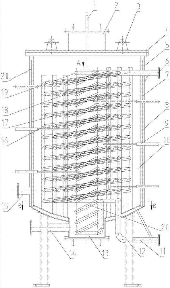
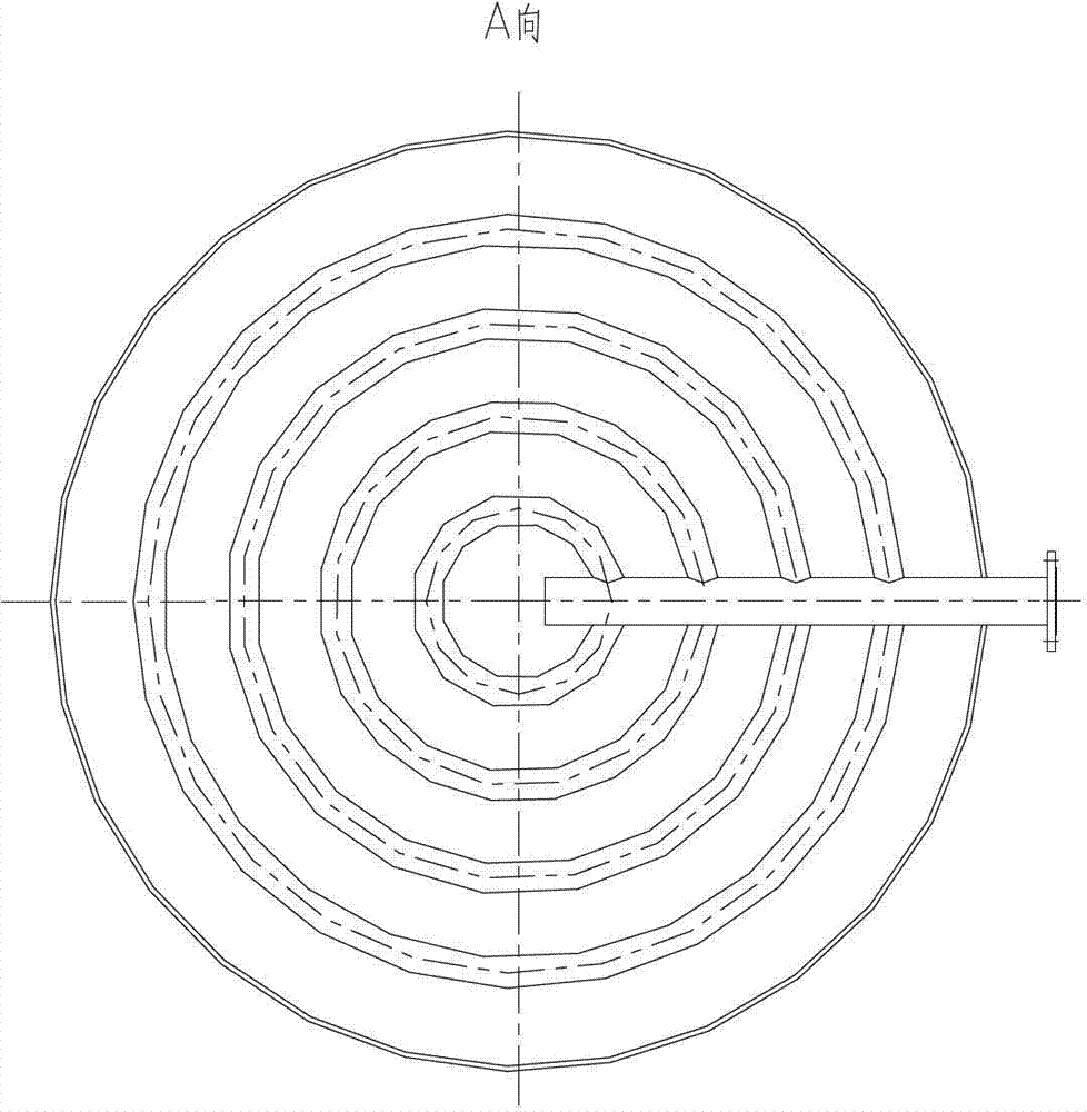
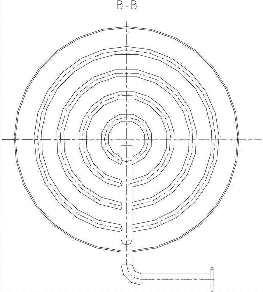
[0027] Example 1: A single-tank phase-change heat storage device for solar energy, see figure 1 , figure 2 , image 3 , there are breathing port 1, heat storage medium feed port 2, upper cover 4, heat storage medium discharge port 13, heat storage medium discharge port 14 on the tank body, and multi-ring multi-layer heat exchange is arranged in the tank body Coil, the multi-ring multi-layer heat exchange coil is arranged in parallel between the heat transfer medium outlet pipe 6 at the upper end of the heat exchange coil and the heat transfer medium inlet pipe 11 at the lower end of the heat exchange coil to form a heat transfer medium circulation pipe, The flow direction in the formed heat transfer medium flow channel is bottom-in and top-out. The tank body is surrounded by the inner wall 8, the upper cover 4 and the discharge port 14 of the heat storage medium to form a heat storage chamber, which contains a heat storage medium 10, and the heat exchange between the heat t...

Embodiment 2

[0036] Embodiment 2: In the single-tank phase-change heat storage device for solar energy, a vertical pipe is provided at the center of the coil and connected in parallel with each layer of coil. All the other structures are the same as in Example 1.

Embodiment 3

[0037] Embodiment 3: The single-tank phase-change heat storage device for solar energy also includes the inner wall 8 of the storage tank and the outer wall 5 of the storage tank to form an airtight insulation interlayer 7, which is a vacuum insulation layer, and the outer wall 5 of the storage tank There is a vacuum port 15 on the top, which is connected with the vacuum equipment, and the vacuum degree is 10 -2 Pa. All the other structures are the same as in Example 1. The difference is:

[0038] The diameter of the storage tank is 4m, and the heat exchange coils are distributed in 6 rings in the radial direction, among which the number of coils between the first ring heat exchange coil 16 and the central ring heat exchange coil is 6 rings, and the spacing is equal. The diameter is 20mm.

[0039] The heat storage medium is paraffin heat storage material.

[0040] The heat conduction medium is high-temperature steam, and the steam parameters are: pressure 4MPa, temperature...


PUM


Abstract

The invention belongs to the field of solar energy, relates to the solar-thermal energy thermal storage technology, and in particular relates to a single tank phase change thermal storage device for solar energy. The single tank phase change thermal storage device is characterized in that a respiration port, a thermal storage medium inlet, a upper cover, a thermal storage medium outlet and a thermal storage medium discharge gate are arranged on the tank body, a polycyclic multilayer heat exchange coil is arranged in the tank body, and the polycyclic multilayer heat exchange coil is connected between a heat-transfer medium outlet pipe arranged on the upper end of the heat exchange coil and a heat-transfer medium inlet pipe arranged on the lower end of the heat exchange coil in parallel, thus forming a heat-transfer medium circulation pipeline; a thermal storage chamber of the tank body, which contains the thermal storage mediums, is enclosed by the inner wall, the upper cover and the thermal storage medium discharge gate; a sealed heat insulation sandwich is composed of the inner wall of the storage tank and the outer wall of the storage tank; and a thermometer is arranged in the tank. The device disclosed by the invention has the advantages that the phase change thermal storage technology is adopted to enable the thermal storage density to be improved greatly, and the thermal storage volume is efficiently reduced on the premise of same thermal storage capacity; and the storage and release processes of the phase change materials heat are carried out in the same device, thus simplifying the structure of thermal storage device efficiently, and reducing the cost.

Description

technical field [0001] The invention belongs to the field of solar energy, and relates to solar thermal energy heat storage technology, in particular to a solar single-tank phase-change heat storage device. Background technique [0002] Solar energy refers to the radiant energy of the sun. The main utilization forms of solar energy are photoelectric conversion, photothermal conversion and photochemical conversion of solar energy. Solar photovoltaic power generation converts solar radiation into electrical energy through photoelectric conversion; solar thermal utilization uses solar radiation to heat water, or generates steam to provide steam for industrial process heat or steam turbine power generation. In summary, solar energy has the following advantages: (1) Universal: the sun shines on the earth, without geographical restrictions, no matter land or sea, no matter mountains or islands, it is everywhere, can be directly developed and utilized, and does not need to be mine...

Claims


Application Information

Patent Timeline
Patent Type & Authority Applications(China)
IPC IPC(8): F24J2/34F24J2/30F24J2/46F24S10/30
CPCY02E10/44
Inventor 范多旺王成龙范多进杨树本
Owner 兰州大成科技股份有限公司
Why Eureka
Try Eureka