
Industrial glass fiber fabric coating device

A glass fiber, coating device technology, applied in the device, coating, textile and paper making of the surface coating liquid, can solve the problems affecting the quality of the finished product, air bubbles, function and single structure, etc., to avoid the suction force Insufficient, high dust removal efficiency, good coating quality effect

Inactive Publication Date: 2020-12-11
嘉兴杰特新材料股份有限公司
View PDF8 Cites 3 Cited by
  • Summary
  • Abstract
  • Description
  • Claims
  • Application Information

AI Technical Summary

Problems solved by technology

[0003] At present, direct methods are commonly used to form polymer coatings on the surface of glass fiber fabrics. Therefore, the quality of fabric surface coatings depends largely on the coating device. The current coating device has a single function and structure, mainly using The material roller is carried out in the form of dipping the solution in the polymer solution and rolling the fabric, because the viscosity of the polymer melted state is high and needs to be stirred continuously, so that bubbles are generated inside the solution and it is difficult to overflow. The remaining air bubbles on the surface of the fabric cannot be discharged in time, which will affect the performance of the final fabric product
On the other hand, the glass fiber fabric as the base layer needs to be dust-removed before coating. If the dust-removal effect is not good, the dust residue on the fabric surface will also produce bubbles in the polymer coating on the fabric surface during the coating process, which will affect the quality of the finished product.

Method used


Image

  • Industrial glass fiber fabric coating device
  • Industrial glass fiber fabric coating device
  • Industrial glass fiber fabric coating device

Examples


Embodiment

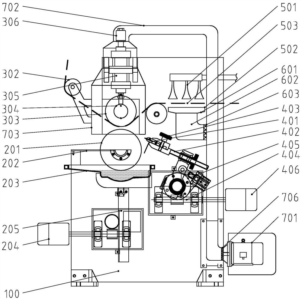
[0026] Such as figure 1 An industrial glass fiber fabric coating device shown includes a frame 100 and a coating roller assembly arranged on the frame, a feeding roller assembly, a thickness-setting doctor blade assembly, a front ash removal assembly and a negative pressure assembly, and the feeding roller The assembly is arranged above the coating roller assembly, the thickness-setting scraper assembly is arranged on the side of the coating roller assembly, and the front ash removal assembly is arranged on the feeding side of the feeding roller assembly. The function of the negative pressure component is to generate negative pressure at the coating working part of the glass fiber fabric, so that the residual air bubbles in the polymer solution at the coating site can be quickly precipitated, so that the quality of the final coating is better, and the air suction direction is From the coating layer of the glass fiber fabric to the back of the fabric, after the polymer solution...


PUM


Abstract

The invention provides an industrial glass fiber fabric coating device capable of effectively eliminating bubbles in the coating process. The industrial glass fiber fabric coating device comprises a rack, a coating roller assembly, a conveying roller assembly, a fixed-thickness scraper assembly, a front ash removal assembly and a negative pressure assembly, wherein the coating roller assembly, theconveying roller assembly, the fixed-thickness scraper assembly, the front ash removal assembly and the negative pressure assembly are arranged on the rack, the front ash removal assembly comprises asonic ash blower and a negative pressure dust removal pipeline which are arranged oppositely, a feeding channel is arranged between the sonic ash blower and the negative pressure dust removal pipeline, and one end of the negative pressure dust removal pipeline communicates with the negative pressure assembly; and the negative pressure assembly comprises a vacuum pump, an air suction main pipe anda negative pressure cover, the vacuum pump communicate with the negative pressure cover through the air suction main pipe, the negative pressure cover is arranged above the coating roller assembly and a back roller in a covering mode, and the middle of the air suction main pipe communicates with the negative pressure dust removal pipeline. According to the device, the negative pressure assembly enables the coating working portion of a glass fiber fabric to generate negative pressure, the residual bubbles in a polymer solution at the coating position are rapidly separated out, and the qualityof the finally formed coating is better.

Description

technical field [0001] The invention relates to a coating device, in particular to an industrial glass fiber fabric coating device. Background technique [0002] Glass fiber is an inorganic non-metallic material with excellent performance. It has various types and has the characteristics of good insulation, strong heat resistance, good corrosion resistance and high mechanical strength. Through weaving process, glass fiber can be made into various fabrics. Such as glass cloth, glass ribbon, unidirectional fabric, three-dimensional fabric, knitted felt, etc. However, due to the disadvantages of brittleness and poor wear resistance of glass fibers, the surface of the fabricated fabric requires a polymer coating to improve the performance of the fabric. Generally speaking, the formation of fabric coating has the following methods: 1. Direct method. The direct method is to flatten the fabric to form a uniform plane, and then let the fabric pass under a static scraper, and the sc...

Claims


Application Information

Patent Timeline
Patent Type & Authority Applications(China)
IPC IPC(8): B05C1/08B05C9/10B05D3/04D06G1/00
CPCB05C1/0817B05C1/083B05C9/10B05D3/0406D06G1/00
Inventor 谈栋立张玉江王军沈海平金志达叶晓铭崔超强
Owner 嘉兴杰特新材料股份有限公司
Learn More