Cold extrusion forming process of helical gear

A forming process and cold extrusion technology, applied in metal extrusion, metal extrusion dies, wheels, etc., can solve the problems of selecting spring type and strength, high gear precision requirements, insufficient tooth shape and tooth direction, etc. Eliminate the effect of elastic deformation

Inactive Publication Date: 2020-12-11
SHANGHAI AUTOMOBILE GEAR WORKS
View PDF24 Cites 1 Cited by
  • Summary
  • Abstract
  • Description
  • Claims
  • Application Information

AI Technical Summary

Problems solved by technology

Because the helical gear has a spiral groove, its structure is complex, and the gear precision is high. At present, the main processing methods such as hobbing, shaping, grinding or honing are used, but the following problems exist in machining: many processes, low material utilization, Slow processing efficiency and high production cost
This forming method is still a form of one-way force in essence. The force of the spring depends on the output force of the hydraulic system of the equipment and cannot be adjusted according to the actual situation. Tests have proved that this structure still has tooth shape and tooth direction. Insufficient situation
In addition, because the type and strength of the spring cannot be accurately selected through calculation, the stability of the extrusion molding quality will be affected due to the aging of the spring in mass production

Method used


Image

  • Cold extrusion forming process of helical gear
  • Cold extrusion forming process of helical gear
  • Cold extrusion forming process of helical gear

Examples


Embodiment Construction

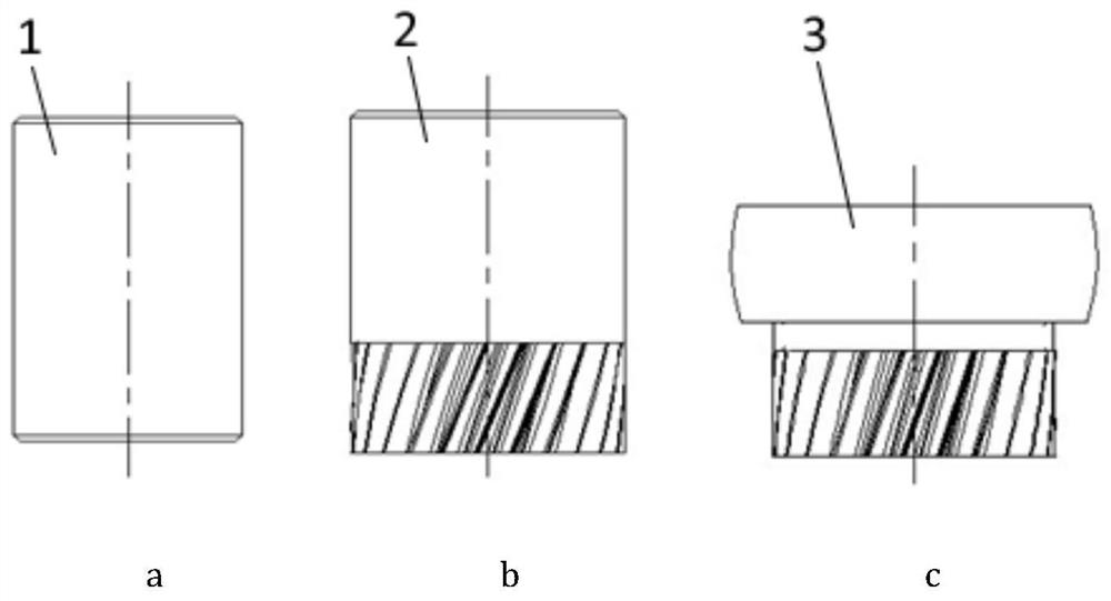
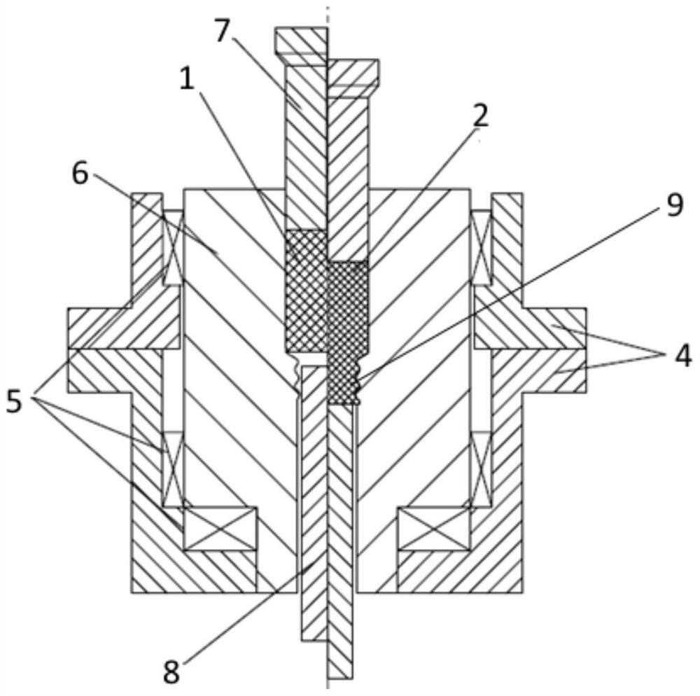
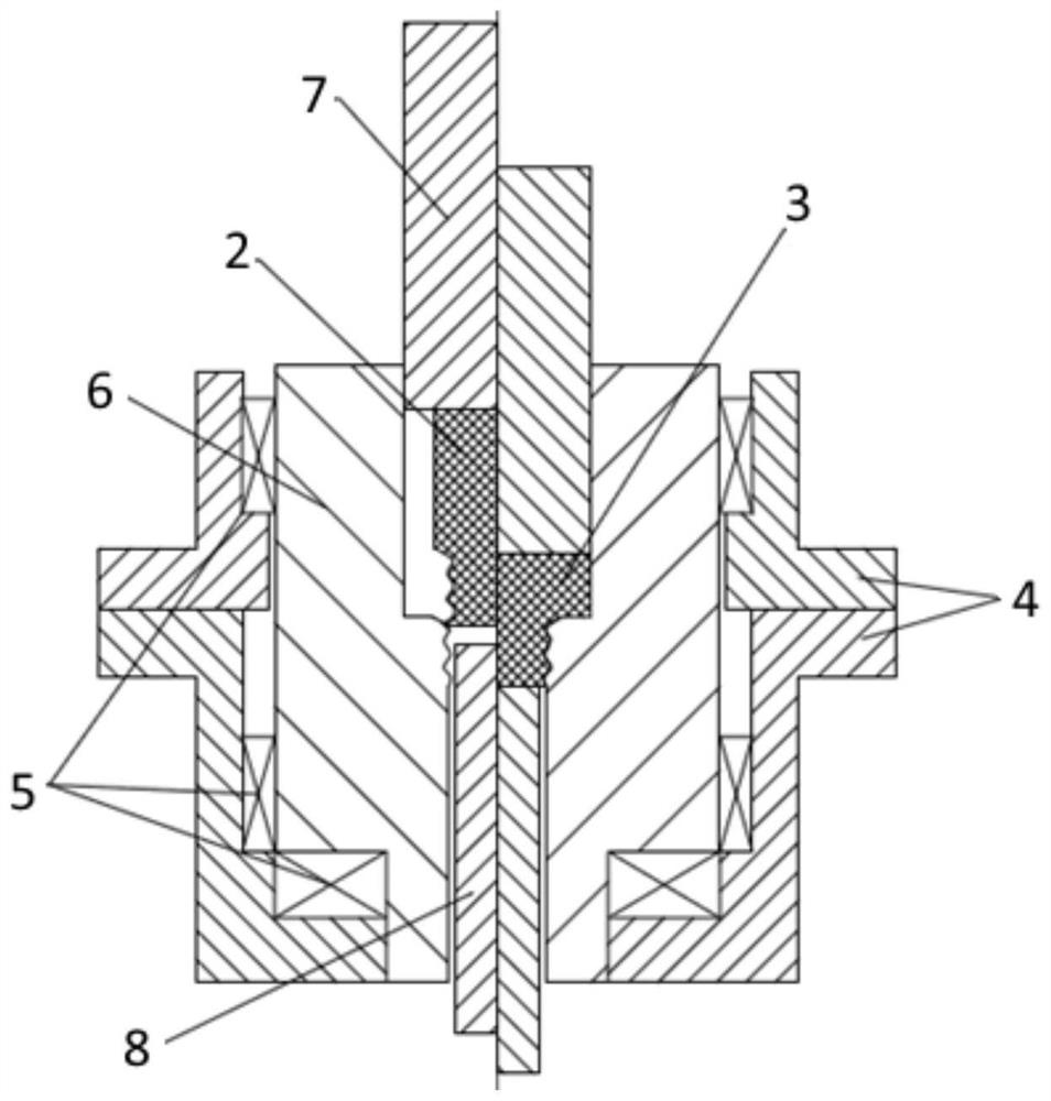
[0033] Such as figure 2 As shown, the cold extrusion die involved in this embodiment includes: a mold cylinder 4, a die 6, an upper punch 7 and a lower ejector pin 8 arranged in sequence from outside to inside, wherein: between the mold cylinder 4 and the die 6 A bearing 5 is provided, an upper punch 7 and a lower ejector rod 8 are correspondingly arranged and connected with the upper and lower hydraulic systems, and the bar material 1 is located between the upper punch 7 and the lower ejector rod 8 .

[0034] The center of the said die 6 is provided with a helical tooth groove 9 .

[0035] The mouth of the tooth groove of the cold extrusion die 6 is provided with a positioning hole and a guide hole, wherein: the gap between the bottom diameter of the tooth groove of the positioning hole, the two sides of the tooth and the outer diameter of the preformed blank tooth is 0.1mm, The depth is 2-4mm, and the depth direction of the positioning hole is not provided with a bevel; th...


PUM


Abstract

The invention discloses a cold extrusion forming process of a helical gear. The cold extrusion forming process specifically comprises the following steps: (1) spheroidizing annealing, shot blasting and phosphorus saponification treatment are sequentially conducted on a bar; (2) the bar treated in the step (1) is placed in a cold extrusion die to enable the bar to form a forming blank with a required spiral gear groove; (3) the formed blank in the step (2) is placed in an upset-extrusion forming die, the head of the blank is upset, and a forged piece is obtained; and (4) the forged piece in thestep (3) is subjected to isothermal normalizing treatment, so that the gear meets the technical requirements of products. According to the preparation method, a rotary lower die structure is adopted,a lower die freely rotates under the action of radial force generated when materials flow, and therefore the requirement for forming a spiral angle is met; the extrusion speeds of three strokes are adopted, so that the gear profile of a part is completely filled; and two sets of hydraulic systems are adopted, so that elastic deformation and friction deformation of gear sides caused by demolding are eliminated.

Description

technical field [0001] The invention relates to a technology in the field of cold extrusion of gears, in particular to a cold extrusion forming process of helical gears. Background technique [0002] Gears are widely used in automobile transmission. Because the helical gear has a spiral groove, its structure is complex, and the gear precision is high. At present, the main processing methods such as hobbing, shaping, grinding or honing are used, but the following problems exist in machining: many processes, low material utilization, The processing efficiency is slow and the production cost is high. [0003] The use of cold extrusion molding can make up for the lack of mechanical processing. Through the movement of equipment pressure, the bar to be extruded is pressed into the cavity with spiral tooth grooves, and the metal material flows along the tooth grooves to form helical gears. This cold extrusion method can be divided into non-resistance extrusion and resistance extr...

Claims


Application Information

Patent Timeline
Patent Type & Authority Applications(China)
IPC IPC(8): B21C23/14B21C25/02B21C26/00B21C35/02B21K1/30
CPCB21C23/14B21C25/02B21C26/00B21C35/02B21K1/30
Inventor 张晖李文辉曾晓蕾刘目娟楚大锋
Owner SHANGHAI AUTOMOBILE GEAR WORKS
Why Eureka
Try Eureka