
Automatic demolding device for aluminum material machining

An automatic demoulding and aluminum material technology, applied in metal processing equipment, forging/pressing/hammer devices, manufacturing tools, etc., can solve the problems of low work efficiency, low degree of automation, waste of manpower, etc., to improve work efficiency and automation High degree of manpower and time saving effect

Inactive Publication Date: 2020-12-11
杨秀波
View PDF0 Cites 0 Cited by
  • Summary
  • Abstract
  • Description
  • Claims
  • Application Information

AI Technical Summary

Problems solved by technology

However, the demoulding of existing aluminum processing is mainly carried out manually, which wastes a lot of manpower, low work efficiency and low degree of automation

Method used


Image

  • Automatic demolding device for aluminum material machining
  • Automatic demolding device for aluminum material machining
  • Automatic demolding device for aluminum material machining

Examples


Embodiment 1

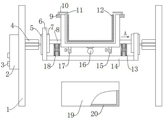
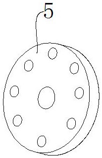
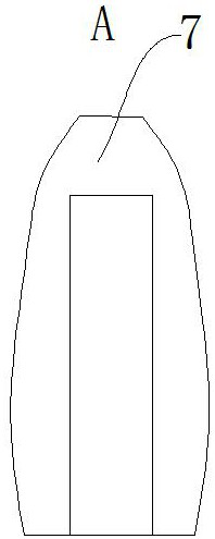
[0033] Such as Figure 1-Figure 4 As shown, an automatic demoulding device for aluminum processing includes a column 1, a control box 2, an operation button 3, a first motor 4, and a connecting disc 5. A control box 2 is arranged on one side of the column 1, and the control box 2 is An operation button 3 is provided, a first motor 4 is provided on the other side of the column 1, and the first motor 4 is used to provide power. One side of the first motor 4 is provided with a connecting disc 5, and one side of the connecting disc 5 is provided Side plate 6 is arranged, and one side of side plate 6 is provided with slideway 7, and the lower end of side plate 6 is provided with bottom plate 14, and one side of slideway 7 is provided with connecting baffle plate 8, and one side of connecting baffle plate 8 is provided with take-off Die bucket 11, demoulding bucket 11 is used for containing mold 12, and the inboard of demoulding bucket 11 is provided with mold 12, and the lower end ...

Embodiment 2

[0035] The difference between this embodiment and embodiment 1 is:

[0036] The column 1 and the control box 2 are connected by screws, which make it easy to install and fix. The column 1 and the first motor 4 are connected by bolts, which ensure a certain connection strength and are easy to disassemble and connect the baffle. 8 and block 18 are connected by welding, which makes the connection between the two tight and firm.

[0037]Working principle: connect the water inlet pipe 15 with the external water source, inject cooling water into the gap between the demoulding barrel 11 and the mold 12, after a period of time, open the water outlet pipe 17, drain the moisture inside the demoulding barrel 11, and start Vibrating motor 16, under the action of vibrating motor 16, mold 12 reciprocates up and down in the demoulding barrel 11, finally separates from demoulding barrel 11, closes vibrating motor 16, starts second motor 9, and second motor 9 rotates to drive the rotating bloc...


PUM


Abstract

The invention discloses an automatic demolding device for aluminum material machining. The automatic demolding device comprises stand columns, a control box, operation buttons, a first motor and a connecting disc. The control box is arranged on one side of one stand column, the operation buttons are arranged on the control box, and the first motor is arranged on the other side of the stand column.The connecting disc is arranged on one side of the first motor, a side plate is arranged on one side of the connecting disc, a sliding way is arranged on one side of the side plate, a bottom plate isarranged at the lower end of the side plate, and a connecting baffle is arranged on one side of the sliding way. The automatic demolding device has the beneficial effects that a vibration motor is arranged at the lower end of a demolding barrel, so that the demolding barrel is separated from a mold through vibration of the vibration motor, the mold is rapidly cooled by adding cooling water into agap between the demolding barrel and the mold so as to be separated from the demolding barrel, the device is high in automation degree, a large amount of manpower and time are saved, and working efficiency is improved.

Description

technical field [0001] The invention relates to the technical field of demoulding devices, in particular to an automatic demoulding device for processing aluminum materials. Background technique [0002] Aluminum alloy profiles are the most widely used non-ferrous metal structural materials in the industry. They have been widely used in aviation, aerospace, automobiles, machinery manufacturing, ships, construction, decoration, and chemical industries. With the development of science and technology and industrial economy in recent years With the rapid development of aluminum alloy, the demand for welded structural parts of aluminum alloy is increasing day by day, so that the research on weldability of aluminum alloy is also in-depth. The wide application of aluminum alloy promotes the development of aluminum alloy welding technology, and the development of welding technology expands Therefore, the welding technology of aluminum alloy is becoming one of the research hotspots. ...

Claims


Application Information

Patent Timeline
Patent Type & Authority Applications(China)
IPC IPC(8): B21J13/14B21J13/02B21K29/00
CPCB21J13/02B21J13/14B21K29/00
Inventor 杨秀波
Owner 杨秀波
Learn More