Processing method for push rod connecting base

A processing method and connecting seat technology, applied in metal processing equipment, metal processing mechanical parts, manufacturing tools, etc., can solve the problems of slow drilling, ineffective control, affecting production progress, etc., to achieve accurate drilling positioning and improve efficiency Effect

Inactive Publication Date: 2020-12-11
CHINA COAL BEIJING COAL MINING MACHINERY
View PDF5 Cites 1 Cited by
  • Summary
  • Abstract
  • Description
  • Claims
  • Application Information

AI Technical Summary

Problems solved by technology

[0003] At present, the main method is to lower the speed of the drilling machine, the fitter will grind the end faces of the inlet and outlet flat, and drill slowly at low speed. This method can reduce the problem of drilling deviation of parts, but it cannot be effectively controlled, and the processing efficiency is too slow, which seriously affects production progress

Method used


Image

  • Processing method for push rod connecting base
  • Processing method for push rod connecting base
  • Processing method for push rod connecting base

Examples


specific Embodiment

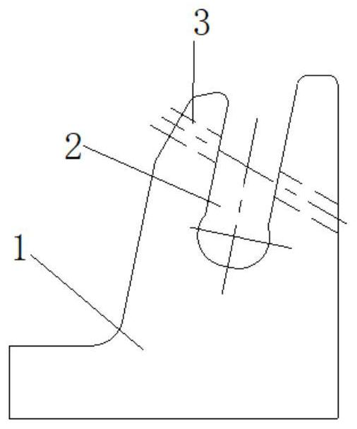
[0022] Such as Figure 1a , Figure 1b As shown, the connecting seat of the push rod is generally formed by blanking steel plates made of Q550 and Q690, and the U-shaped groove is mostly in the form of an inclined groove. At the same time, the pin hole is also in the form of an inclined hole. Hole, place the connecting seat on the tooling of the inclined hole to ensure the vertical direction of the hole, which is convenient for drilling. However, the U-shaped groove is in the form of a beveled edge, and the material hardness is relatively high. The front end of the drill bit has no guide, which may easily cause the drill bit to deviate when entering the hole, resulting in problems such as misalignment of the hole and deviation.

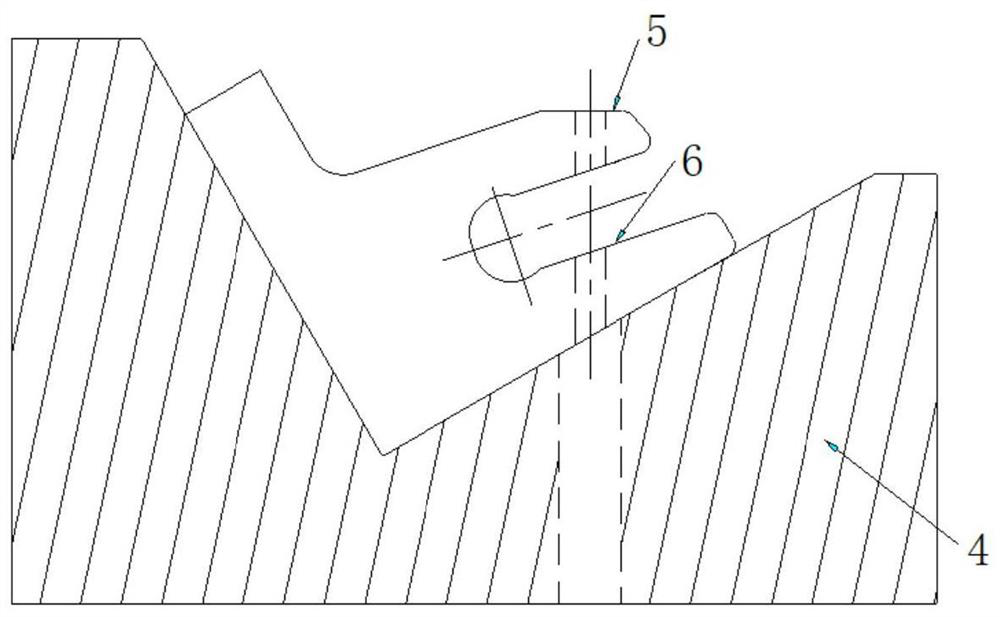
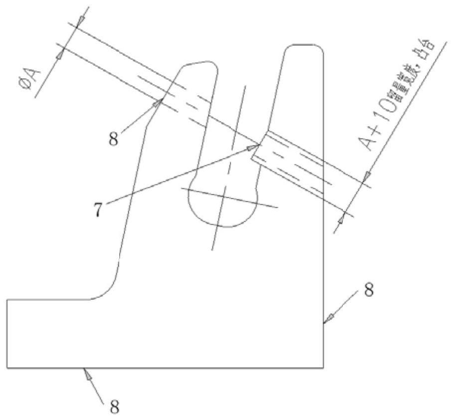
[0023] Such as Figure 2a , Figure 2b As shown, by adjusting the shape of the U-shaped groove of the connecting seat and increasing the platform where the drill bit enters the hole, the positioning accuracy during drilling can be ensured.

[0024]...


PUM


Abstract

The invention discloses a processing method for a push rod connecting base. An inclined U-shaped groove and an inclined hinge pin hole are formed in the push rod connecting base, and the blank of thepush rod connecting base is arranged on a slope hole tool; it is ensured that the hinge pin hole to be machined is in the vertical direction, and drilled with a drill bit vertically; and a drill bit inlet of the hinge pin hole to be machined is processed into a plane; the drill bit is perpendicular to the plane; and a boss plane is reserved at the drill bit inlet of the inner wall of the U-shapedgroove, so that the drill bit is perpendicular to the boss plane. When the push rod connecting base is used for blanking and cutting, 3mm tool detection machining allowance is reserved on each of three cut surfaces, and the tool detection surfaces are used as reference surfaces for subsequent machining. Through regulation of the profile machining allowance of the connecting base, the plane for drilling the inclined hole is added, and it is ensured that an inclined location hole is a straight platform plane and is used in cooperation with an inclined hole machining tool; and it is ensured thatthe drilling location is accurate, and the machining drilling efficiency is effectively improved.

Description

technical field [0001] The invention relates to a processing technology for a push rod connecting seat of a coal mine fully mechanized mining hydraulic support, in particular to a processing method for a push rod connecting seat. Background technique [0002] The pushing rod plays the role of pushing the support in the fully mechanized mining hydraulic support, so the structure and overall strength of the pushing rod are relatively high, and the assembly clearance and size control must be strictly required in the production process. As an important part of the push rod, the connecting seat of the push rod plays the role of positioning and locking the push jack. However, the inclined hole processing on the connecting seat is made of high hardness material, which is the most difficult. Directly drilling through a drilling machine will cause too much deviation of the inclined hole. It is difficult to meet the assembly size. In order to improve the positioning accuracy of the in...

Claims


Application Information

Patent Timeline
IPC IPC(8): B23B35/00B23B41/00B23P15/00B23Q3/00
CPCB23B35/00B23B41/00B23P15/00B23Q3/00
Inventor 刘爱民王震高美聪刘蕴熙李永峰
Owner CHINA COAL BEIJING COAL MINING MACHINERY
Why Eureka
Try Eureka