
Machining equipment used for producing special-shaped ornaments and having automatic drilling and polishing functions

A technology for processing equipment and ornaments, which is applied in the field of processing equipment with automatic drilling and grinding functions for the production of special-shaped ornaments, can solve problems such as asymmetry and loss of swing arms, and achieve the effect of avoiding errors.

Pending Publication Date: 2020-12-11
东莞市优伟机电科技有限公司
View PDF0 Cites 2 Cited by
  • Summary
  • Abstract
  • Description
  • Claims
  • Application Information

AI Technical Summary

Problems solved by technology

[0003] Usually, the symmetry between the two sides of the screw hole and the fine hole of the swing arm is one of the difficulties in processing. However, the drilling and tapping are divided into two parts for operation, and the material is manually loaded and unloaded by personnel, which will inevitably cause problems. There are errors, which lead to loss of asymmetry on both sides of the swing arm during processing. Therefore, we provide a processing equipment with automatic drilling and grinding functions for the production of special-shaped ornaments

Method used


Image

  • Machining equipment used for producing special-shaped ornaments and having automatic drilling and polishing functions
  • Machining equipment used for producing special-shaped ornaments and having automatic drilling and polishing functions
  • Machining equipment used for producing special-shaped ornaments and having automatic drilling and polishing functions

Examples


Embodiment Construction

[0027] The following will clearly and completely describe the technical solutions in the embodiments of the present invention with reference to the accompanying drawings in the embodiments of the present invention. Obviously, the described embodiments are only some, not all, embodiments of the present invention.

[0028] In the description of the present invention, unless otherwise stated, the meaning of "plurality" is two or more; the terms "upper", "lower", "left", "right", "inner", "outer" , "front end", "rear end", "head", "tail", etc. indicate the orientation or positional relationship based on the orientation or positional relationship shown in the drawings, and are only for the convenience of describing the present invention and simplifying the description, rather than Indicates or implies that the device or element referred to must have a particular orientation, be constructed and operate in a particular orientation, and therefore should not be construed as limiting the...


PUM


Abstract

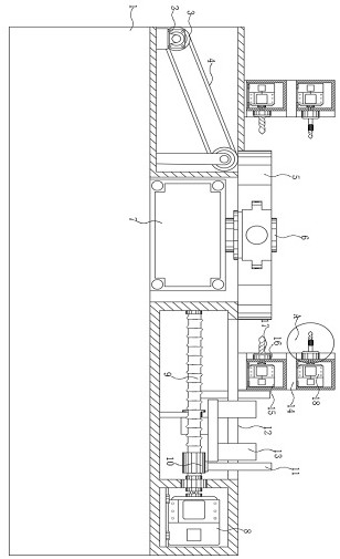
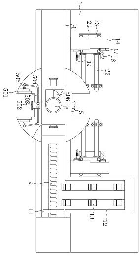
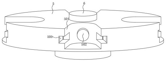
The invention discloses machining equipment used for producing special-shaped ornaments and having automatic drilling and polishing functions. The equipment comprises a bottom case. A first servo motor is installed above the left of an inner cavity of the bottom case. A center shaft is arranged at the centering position of a center line of a rotary clamping base vertically in a transverse penetrating manner. Flow guide grooves are connected above plane overlooking pushing plates of the bottom case. Gap conveying mechanisms are arranged on the middle portions of the flow guide grooves. Slidingcases are symmetrically installed on the rotary clamping base. Controllers are arranged on the bottoms of the sliding cases. Sliding rods are symmetrically arranged on the two sides of the interiors of the controllers. According to the equipment, the gap conveying mechanisms are arranged in the flow guide grooves, the pushing plates on conveying plates of the gap conveying mechanisms are arrangedat equal distance, the ornaments can be moved horizontally and conveniently one by one, meanwhile, by arranging the pushing plates and the rotary clamping base, the ornaments can be conveniently pushed to the rotary clamping base to be rotated to the inner sides of the sliding cases, errors caused by manual feeding and discharging are avoided, and the ornaments are positioned beneficially.

Description

technical field [0001] The invention relates to the technical field of automatic drilling and grinding, in particular to a processing equipment for producing special-shaped ornaments with the function of automatic drilling and grinding. Background technique [0002] The swing rod is the abbreviation of the swing guide rod mechanism, which means that in the guide rod mechanism, the guide rod can only swing back and forth within a certain angle range. Transfer guide rod mechanism. If the guide rod can only swing back and forth within a certain angle range, it is called a swing guide rod mechanism, and its pressure angle is 0. In the swing guide rod mechanism, the rotational motion of the crank is converted into that of the guide rod. Reciprocating swing, so it has the nature of quick return motion. The transmission angle of the swing guide rod mechanism is always 90 degrees, and its pressure angle is 0, which has good force transmission performance. It is often used in planers...

Claims


Application Information

Patent Timeline
IPC IPC(8): B23P23/04B23Q3/06B23Q7/06B23Q15/22
CPCB23P23/04B23Q3/06B23Q7/06B23Q15/22
Inventor 李路云陈杰鹏张柱烜
Owner 东莞市优伟机电科技有限公司
Learn More