
Liquid level detection circuit module based on MCU

A liquid level detection and circuit module technology, which is applied in the field of sampling needles, can solve the problems of misjudgment of whether the sampling needle is in contact with the sample liquid surface, increase the cross-contamination of the test object, and greatly fluctuate the capacitance value. Anti-interference ability, fast sampling speed, and the effect of suppressing radiation interference

Pending Publication Date: 2020-12-11
AUTOBIO LABTEC INSTR CO LTD
View PDF0 Cites 2 Cited by
  • Summary
  • Abstract
  • Description
  • Claims
  • Application Information

AI Technical Summary

Problems solved by technology

At present, since in vitro diagnostic instruments and their sample needles are mostly designed as a set, the integrated chip is used to detect the capacitance value for liquid level detection, and the difference between the contact liquid surface and the front and back is used to determine whether the liquid level is in contact. Therefore, the detection range is relatively small. small, poor versatility
And because the measuring range is small, during the dilution test, there is diluent in the sample needle, which causes the detected capacitance value to fluctuate greatly, resulting in misjudgment of whether the sample needle is in contact with the sample liquid surface
At the same time, the existing in vitro diagnostic instruments are very slow when detecting and sampling the liquid level, resulting in a long length of the sampling needle submerged in the liquid level, which increases the cross-contamination between the analytes

Method used


Image

  • Liquid level detection circuit module based on MCU
  • Liquid level detection circuit module based on MCU
  • Liquid level detection circuit module based on MCU

Examples


Embodiment Construction

[0031] The embodiments of the present invention will be described in detail below in conjunction with the accompanying drawings. This embodiment is implemented on the premise of the technical solution of the present invention, and detailed implementation methods and specific operating procedures are provided, but the scope of protection of the present invention is not limited to the following Described embodiment.

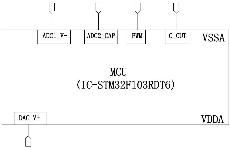
[0032] Such as Figure 1-4 As shown, the MCU-based liquid level detection circuit module of the present invention includes the following units:

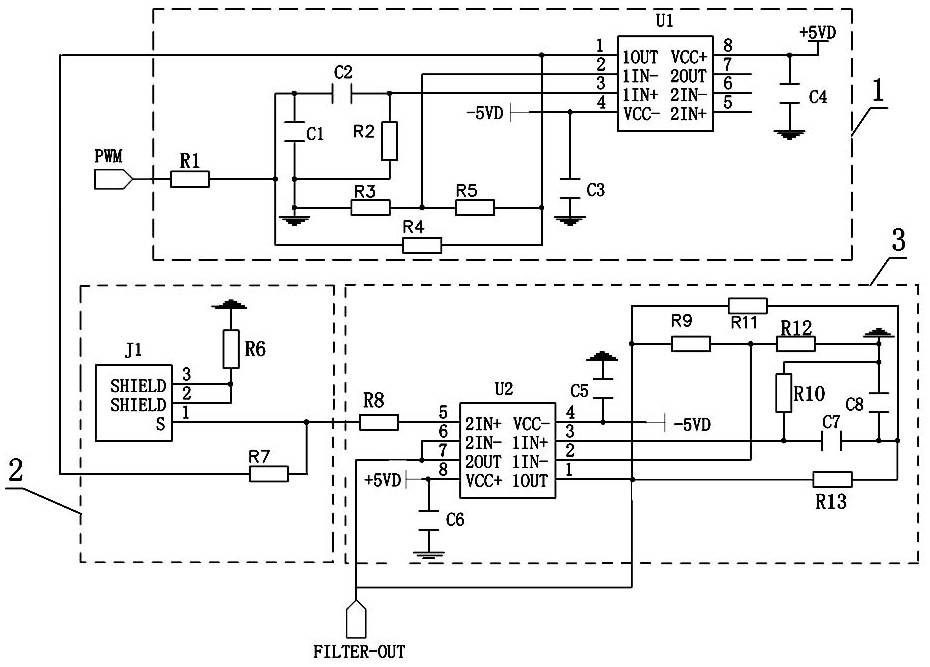
[0033] The sine wave generating unit is used to receive the PWM square wave output by the MCU, and convert the PWM square wave into a sine wave signal through a band-pass filter and output it to the voltage dividing unit. The sine wave generating unit 1 includes a first operational amplifier U1, the positive input terminal (1IN+) of the first operational amplifier U1 is connected to the PWM square wave output terminal of...


PUM


Abstract

The invention discloses a liquid level detection circuit module based on an MCU. The module comprises the following components of: a sine wave generation unit which is used for receiving a PWM squarewave outputted by the MCU, converting the PWM square wave into a sine wave signal, and outputting the sine wave signal; a voltage division unit used for receiving the sine wave signal and performing resistance voltage division on the sine wave signal and a capacitance value signal of a detected liquid level, and outputting the sine wave signal; a voltage following and band-pass filter unit used for carrying out band-pass filtering on the received sine wave signal subjected to resistance voltage division and then outputting the sine wave signal; a first rectifying and filtering unit used for rectifying and filtering the received sine wave signal into a direct current signal; an instrument operational amplifier unit used for executing a liquid level detection instruction sent by the MCU; a second rectifying and filtering unit used for rectifying and filtering the received capacitance value signal and then sending the capacitance value signal to an analog-to-digital conversion interface of the MCU; and a sample adding needle motor control unit used for controlling a sample adding needle motor to work. The liquid level detection circuit module based on the MCU is large in capacitance detection range, high in speed and high in controllability.

Description

technical field [0001] The invention relates to a sampling needle used in an in vitro diagnostic instrument, in particular to an MCU-based liquid level detection circuit module. Background technique [0002] In the in vitro diagnostic instrument, different sample needles exhibit different capacitance values, which requires the in vitro diagnostic instrument to have a large range. At present, since in vitro diagnostic instruments and their sample needles are mostly designed as a set, the integrated chip is used to detect the capacitance value for liquid level detection, and the difference between the contact liquid surface and the front and back is used to determine whether the liquid level is in contact. Therefore, the detection range is relatively small. Small, poor versatility. And because of the small measuring range, during the dilution test, the diluent in the sample needle caused the detected capacitance to fluctuate greatly, resulting in a misjudgment of whether the ...

Claims


Application Information

Patent Timeline
Patent Type & Authority Applications(China)
IPC IPC(8): G01F23/26G01N1/38G01N35/10G05B19/042H03B28/00
CPCG01F23/265G01F23/266G01N1/38G01N35/00584G01N35/10G01N2035/1032G05B19/0423H03B28/00
Inventor 王超耿瑞峰王聪刘森王栋孙海阳聂晶晶刘聪魏文娟
Owner AUTOBIO LABTEC INSTR CO LTD
Learn More