Rubber head shape-preserving device and method for bonding of precision optical-mechanical system

An opto-mechanical and bonding technology, which is applied in the field of precision opto-mechanical design and assembly, can solve the problems of affecting the shape of the bonding area of ​​the bonding area, affecting the surface quality of optical parts, and difficult to constrain the shape of the adhesive, so as to ensure the strength and reduce the Uncontrolled risks, the effect of improving controllability

Active Publication Date: 2020-12-11
西安应用光学研究所
View PDF23 Cites 0 Cited by
  • Summary
  • Abstract
  • Description
  • Claims
  • Application Information

AI Technical Summary

Problems solved by technology

Therefore, when injecting and bonding optical parts and frame parts, the adhesive has a certain fluidity, which affects the bonding area and the shape of the bonding area, resulting in a mismatch between the actual bonding and the designed bonding head, which is serious. Affects the surface quality of optical parts
At present, the method of applying grease is generally used, and grease is applied to the place where the optical parts and the frame do not need to be bonded to prevent this area from gluing. However, due to the flow characteristics of the adhesive, this method is difficult to constrain the shape of the adhesive after curing.

Method used


Image

  • Rubber head shape-preserving device and method for bonding of precision optical-mechanical system
  • Rubber head shape-preserving device and method for bonding of precision optical-mechanical system
  • Rubber head shape-preserving device and method for bonding of precision optical-mechanical system

Examples


Embodiment Construction

[0024] In order to make the purpose, content, and advantages of the present invention clearer, the specific implementation manners of the present invention will be further described in detail below in conjunction with the accompanying drawings and embodiments.

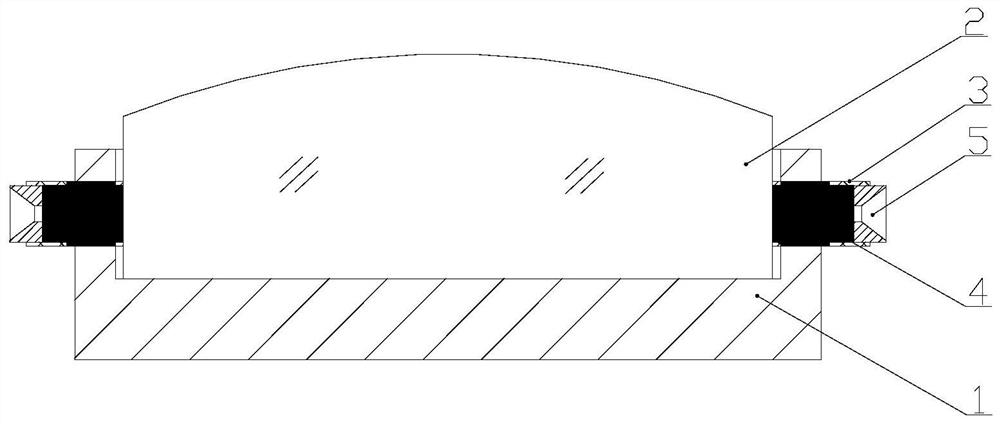
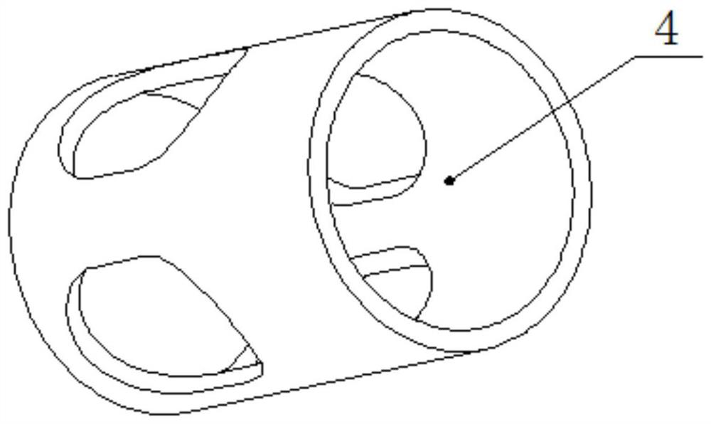
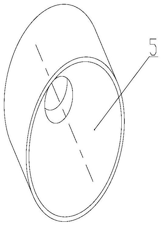
[0025] Such as figure 1 As shown, the glue head shape-preserving device used for precision opto-mechanical system bonding of the present invention includes a main mirror frame 1, an optical part 2, an adhesive 3, a shape-preserving tooling 4 and a plug 5; the optical part 2 is placed on the main mirror frame 1 Inside, the optical axis of the optical part 2 coincides with the central axis of the cylindrical main mirror frame 1; the main mirror frame 1 is provided with a glue injection hole, the shape-preserving tool 4 is closely matched with the glue injection hole, and the inner end surface of the shape-keeping tool 4 is in contact with the optical part 2 is in contact with the outer surface of the shape-keeping toolin...


PUM

PropertyMeasurementUnit
thermal resistanceaaaaaaaaaa
thicknessaaaaaaaaaa

Abstract

The invention discloses a rubber head shape-preserving device and method for bonding of a precision optical-mechanical system. The rubber head shape-preserving device comprises a mirror frame, an optical part, an adhesive, a shape-preserving tool and a plug. The optical part is placed in the mirror frame, the optical axis of the optical part coincides with the cylindrical axis of the mirror frame,the shape-preserving tool is in close fit with a glue pouring hole in the mirror frame, the end face of the shape-preserving tool makes contact with the cylindrical surface of the optical part, the adhesive is injected into the shape-preserving tool, and the plug is installed on the side, away from the optical part, of the shape-preserving tool, and is tightly matched with the shape-preserving tool. When an optical-mechanical bonding assembly is carried out, after the adhesive with fluidity is injected through the shape-preserving tool, the mounting plug slightly extrudes the adhesive to restrain the shape of the adhesive head in the curing process, and the bonding of the optical part and the mirror frame is realized. According to the invention, the risk that the shape of the adhesive head is not easy to control due to high fluidity of the adhesive before curing is reduced, the controllability of the surface shape precision of low-stress bonding of a precision optical-mechanical system is improved, and the method belongs to the field of design, installation and adjustment of precision optical machines.

Description

technical field [0001] The invention belongs to the technical field of precision optical-mechanical design and assembly, and relates to a precision optical-mechanical system bonding tool and method, in particular to a glue head shape-preserving device and method for precision optical-mechanical system bonding. Background technique [0002] Precision optomechanical system bonding technology (Bonding Technique) is to use adhesives to install optical parts on the frame. Due to the low elastic modulus of colloids (such as the elastic modulus of commonly used RTV silicone rubber is 2.2GPa, while aluminum alloy materials and Fused quartz is 70.1GPa and 73GPa respectively), which enables the system to effectively suppress the transmission between the mechanical support part and the optical imaging part under the action of temperature, shock and vibration load, thereby reducing the stress deformation of the optical imaging part and simplifying the system structure. Therefore, bondi...

Claims


Application Information

Patent Timeline
Patent Type & Authority Applications(China)
IPC IPC(8): G02B7/00
CPCG02B7/00
Inventor 王谭黄维东王马强惠进郭冰涛朱辉张卫国庞澜
Owner 西安应用光学研究所
Why Eureka
Try Eureka