
Baud rate identification method and device

A baud rate and time technology, applied in the field of baud rate identification methods and devices, can solve the problems of heavy software burden, inability to automatically correct errors, and difficulty in ensuring identification accuracy, and achieve the effect of improving accuracy and precision

Active Publication Date: 2022-04-15
SHANGHAI EASTSOFT MICROELECTRONICS +1
View PDF9 Cites 0 Cited by
  • Summary
  • Abstract
  • Description
  • Claims
  • Application Information

AI Technical Summary

Problems solved by technology

The first method is relatively simple, with high accuracy but low efficiency. It can only be measured when the other party initiates communication, which has strong limitations; the second method is fast, but there is an error in the minimum pulse width of the measurement. After the port is interrupted, the kernel first needs to perform the operation of pushing the stack to save the current operating environment, and then enter the interrupt processing function to read the count value of the timer and calculate the current pulse width time
The process of pushing the stack requires at least 20 instruction cycles. During this period, the timer is still counting, resulting in the measured pulse width time being larger than the actual value. The greater the bus baud rate, the greater the measurement error.
At the same time, every time an I / O port interrupt is triggered, it is necessary to enter the interrupt to read the count value of the timer. At a communication rate of 1Mbps, there is a situation where an interrupt is triggered every 1 microsecond, resulting in a large software burden and easy loss of waveform data. have an impact on the calculation results
[0004] The above two methods only use the minimum pulse width time to calculate the baud rate, and cannot automatically correct errors. In the case of large minimum pulse width errors and clutter interference or symbol superposition, the recognition accuracy is difficult to guarantee

Method used

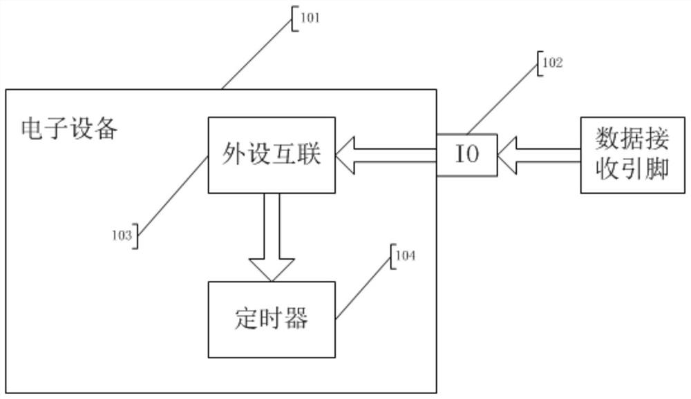
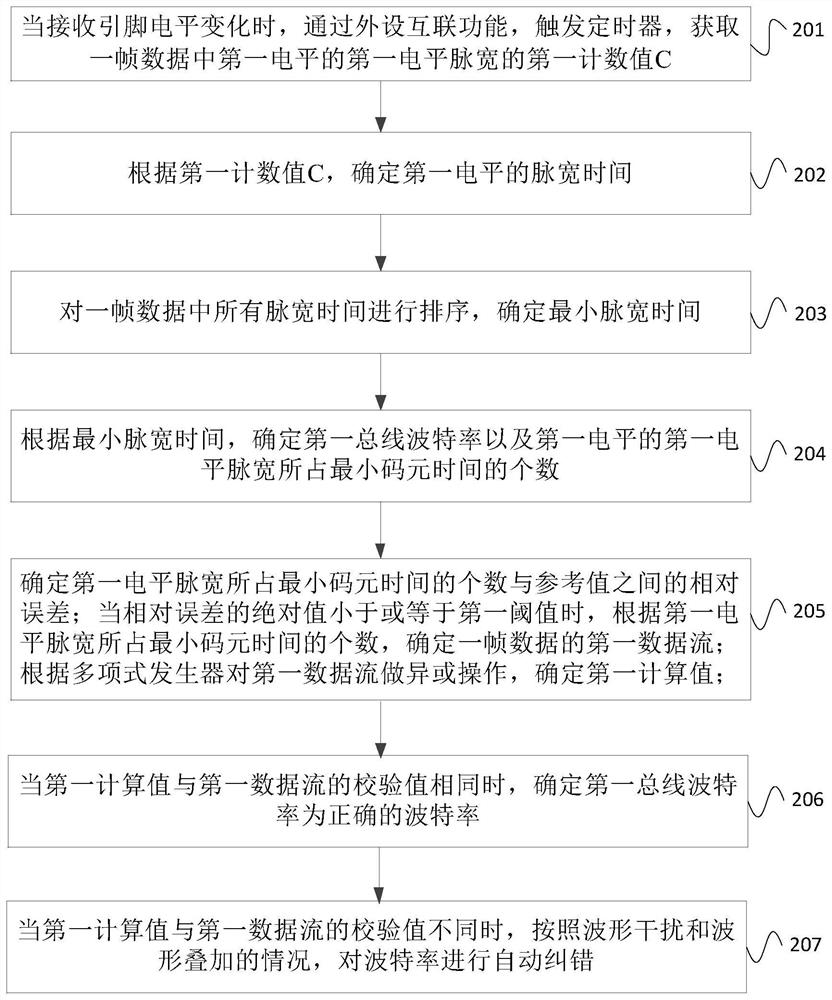

Image

  • Baud rate identification method and device
  • Baud rate identification method and device
  • Baud rate identification method and device

Examples


Embodiment Construction

[0066] In order to make the purpose, technical solutions and advantages of the embodiments of the present invention clearer, the technical solutions in the embodiments of the present invention will be clearly and completely described below in conjunction with the drawings in the embodiments of the present invention. Obviously, the described embodiments It is a part of embodiments of the present invention, but not all embodiments. Based on the embodiments of the present invention, all other embodiments obtained by persons of ordinary skill in the art without making creative efforts belong to the protection scope of the present invention.

[0067] The terms "first", "second", "third", "fourth", etc. (if any) in the description and claims of the present invention and the above drawings are used to distinguish similar objects and not necessarily Describe a particular order or sequence. It is to be understood that the data so used are interchangeable under appropriate circumstance...


PUM


Abstract

The present invention provides a baud rate identification method and device. The baud rate identification method provided in this embodiment includes: when the level of the receiving pin changes, the timer is triggered through the interconnection function of the peripherals to obtain the baud rate in a frame of data. The first count value C of the first level pulse width of the first level; according to the first count value C, determine the pulse width time of the first level; then determine the minimum pulse width time; determine the first bus baud rate and The number of the minimum symbol time occupied by the first level pulse width of the first level; determine the relative error between the number of the minimum symbol time occupied by the first level pulse width and the reference value; For the first threshold value comparison, corresponding different processing is performed according to the difference of the comparison result, and finally the correct baud rate is obtained. Through the baud rate identification method provided by the embodiment of the present disclosure, the correctness verification of the communication baud rate can be realized, thereby improving the accuracy and precision of the baud rate.

Description

technical field [0001] The invention relates to the field of serial bus communication, in particular to a baud rate identification method and device. Background technique [0002] Serial communication adopts the transmission method of data bits. Although it is slower than parallel byte communication, it has a simple structure and low cost. At least one transmission line is needed to complete the transmission. At the same time, the communication range can reach tens of meters. A relatively common form of communication. Since there is no timeline synchronization, devices using serial communication must use the same baud rate, otherwise they cannot communicate. Therefore, in the case of unknown baud rate, an identification method is needed to obtain this important parameter. [0003] In the prior art, there are two common baud rate identification methods. One is the exhaustive method, which changes the baud rate according to a fixed step size within a known range to test whet...

Claims


Application Information

Patent Timeline
Patent Type & Authority Patents(China)
IPC IPC(8): G06F13/32G06F13/42H04L101/627
CPCG06F13/32G06F13/4282H04L2101/627
Inventor 王鹏程袁俊田志伟陈光胜
Owner SHANGHAI EASTSOFT MICROELECTRONICS
Learn More