
Machining device

A machining and workpiece technology, which is applied in the application field of flexible mechanisms in machining, can solve the problems of difficult to achieve buffer support, increase strength, loss of space utilization, etc., and achieve the effect of strong support and strong buffer capacity

Active Publication Date: 2020-12-15
CHANGSHA UNIVERSITY OF SCIENCE AND TECHNOLOGY
View PDF6 Cites 0 Cited by
  • Summary
  • Abstract
  • Description
  • Claims
  • Application Information

AI Technical Summary

Problems solved by technology

[0005] 1. In the flexible mechanism of the prior art, the cells are all connections between complete individuals, but the functional differentiation between cells of different shapes is not considered, and if different cells are connected, the connection between different structural forms Difficulty connecting
[0006] 2. The connection between the cells in the prior art is just a connection, but the connection is not refined, and the connection stiffness and support cannot be guaranteed.
[0007] 3. The ribs in the prior art only serve to increase the strength, but do not consider the direction of force and the bending resistance at all.
[0008] 4. When the flexible mechanism in the prior art is applied, it must be connected to the device with the help of a connecting mechanism, and the adaptability and detachability are not considered.
[0009] 5. The flexible structure of the hydraulic cylinder in the prior art is often just a cushion. If it is thin, it will be easily damaged and the effect will not be good. If it is thick, it will lose space utilization.
[0010] 6. When the flexible mechanism in the prior art is directly used for buffering, there is no additional guiding mechanism, and unexpected deformation of the flexible mechanism in the direction of the offset force is prone to occur
[0011] 7. The cells of the flexible mechanism in the prior art only use the bending deformation to provide the buffer force, and this buffer is only provided by the deformation force in the linear direction, and the effect is only provided by a single force
[0012] 8. Most of the cells of the flexible mechanism in the prior art are composed of several identical cells through linear superposition, so it is difficult to achieve greater buffer support

Method used


Image

  • Machining device
  • Machining device
  • Machining device

Examples


Embodiment Construction

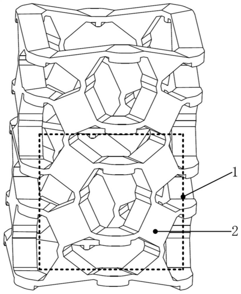
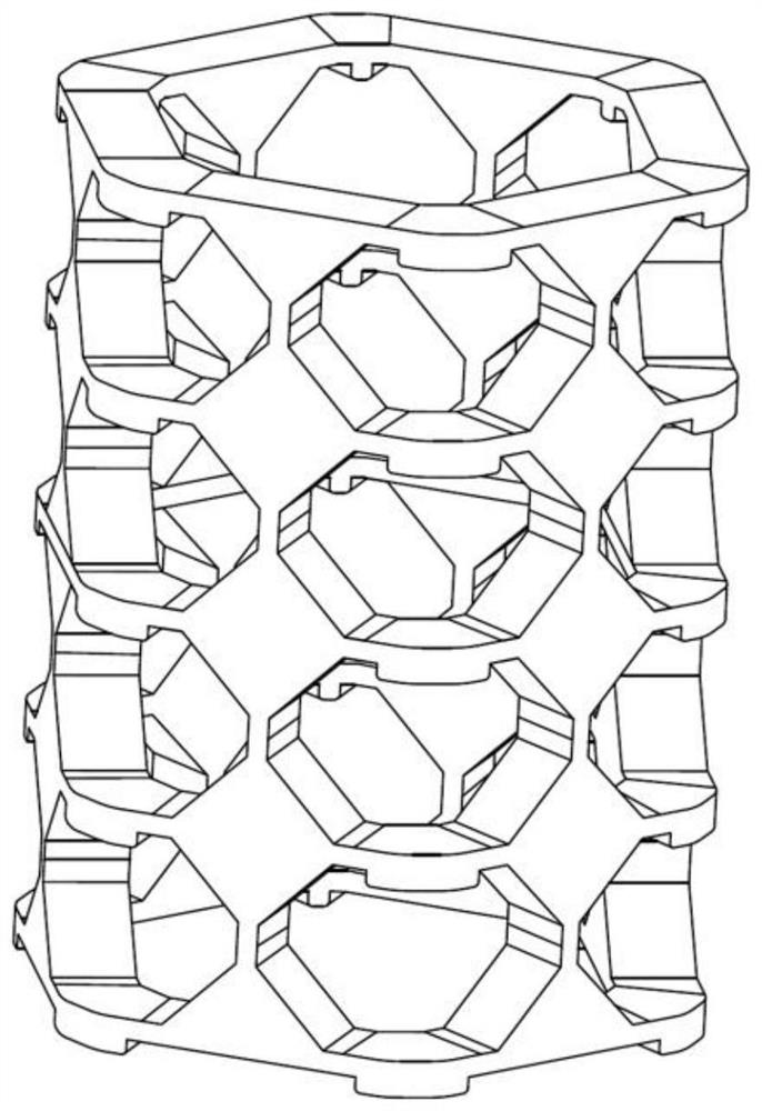
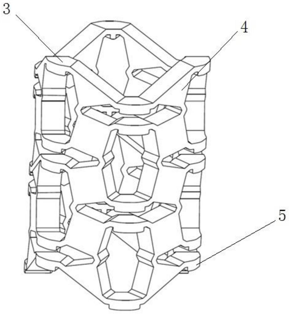
[0050]As shown in the figure: a machining device, including: a worktable 14, a first clamping hydraulic cylinder 15, a second clamping hydraulic cylinder 16, a bracket 17, a driving part 18, a working head 19, and a feed hydraulic cylinder 20; Wherein said support 17 is arranged above said workbench 14, said drive unit 18 is suspended on said support 17 top, said drive unit 18 drives said working head 19 to process workpiece 13, and said workpiece 13 left side is provided with There is a first clamping hydraulic cylinder 15, and a second clamping hydraulic cylinder 16 is provided on the right side; the feed hydraulic cylinder 20 controls the movement of the workpiece 13;

[0051] The first clamping hydraulic cylinder 15, the second clamping hydraulic cylinder 16, and the feeding hydraulic cylinder 20 all include: a cylinder body 11, a driving rod 6, a piston 7, a guide column 9, an oil port 10, a flexible Mechanism 8, connecting sleeve 12; said flexible mechanism 8 is a hollow...


PUM


Abstract

The invention discloses a machining device. The machining device comprises a workbench, a first clamping hydraulic cylinder, a second clamping hydraulic cylinder, a support, a driving part, a workinghead and a feeding hydraulic cylinder, wherein the support is arranged above the workbench, the driving part is hung on the upper portion of the support, the driving part drives the working head to machine a workpiece, the first clamping hydraulic cylinder is arranged on the left side of the workpiece, the second clamping hydraulic cylinder is arranged on the right side of the workpiece, the feeding hydraulic cylinder controls the workpiece to move, and each hydraulic cylinder comprises a cylinder body, a driving rod, a piston, a guide column, an oil port, a flexible mechanism and a connectingsleeve.

Description

technical field [0001] The invention relates to the application field of flexible mechanisms in machining, in particular to a machining device. Background technique [0002] Poisson's ratio is a basic parameter of structural deformation. Poisson's ratio in ordinary materials is generally a positive number, and the range is mostly between 0-0.5. When ordinary materials are stretched in one direction, their cross-section will shrink with stretching, but the cross-section of negative Poisson's ratio materials (auxetic materials) will expand with stretching, such as single crystal sulfide ore, Polytetrafluoroethylene (PTFE) and silica with tetrahedra. [0003] Inspired by the above-mentioned physical properties of negative Poisson’s ratio materials, researchers at home and abroad have designed many different negative Poisson’s ratio structures. When the negative Poisson's ratio structure is under pressure in the axial direction, it will shrink in the axial and radial direction...

Claims


Application Information

Patent Timeline
IPC IPC(8): B23Q3/08
CPCB23Q3/082
Inventor 刘北黄龙胡波徐晓强尹来容
Owner CHANGSHA UNIVERSITY OF SCIENCE AND TECHNOLOGY
Learn More