
Power battery heat dissipation method

A heat dissipation method and power battery technology, applied in secondary batteries, circuits, electrical components, etc., can solve the problems of easy overcooling, low heat removal efficiency, low performance, etc., to improve heat transfer effect and maintain efficient heat removal capability. Effect

Pending Publication Date: 2020-12-15
CHINA PETROLEUM & CHEM CORP +1
View PDF8 Cites 0 Cited by
  • Summary
  • Abstract
  • Description
  • Claims
  • Application Information

AI Technical Summary

Problems solved by technology

[0006] The purpose of the present invention is to overcome the low performance of phase change materials, low heat removal efficiency, flammable, explosive and volatile, relatively low melting point and phase change heat, and easy supercooling in the phase change heat dissipation method of power batteries in the prior art. Disadvantages, the present invention provides a power battery heat dissipation method based on ionic liquid phase change materials, through which the ionic liquid phase change absorbs the heat generated under battery operation or abnormal conditions, and then quickly dissipates the heat through the combination of fins and air cooling. Removal, restoration of heat storage capacity of ionic liquid phase change materials

Method used


Image

  • Power battery heat dissipation method
  • Power battery heat dissipation method
  • Power battery heat dissipation method

Examples


Embodiment 1

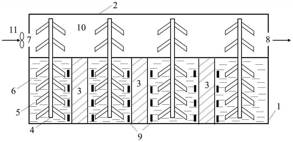
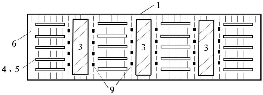
[0060] Such as Figure 1-2 As shown, the power battery cooling device of this embodiment includes a battery box 1 and an air-cooled box 2 that are attached to each other, and 20 cylindrical solid heat-conducting members 4 (heat-conducting pipes).

[0061] Wherein, the battery box 1 includes 3 groups of power batteries 3 (power battery modules) arranged at intervals in the middle and an ionic liquid phase change material 6 filling the surrounding space, and the ionic liquid phase change material 6 is used to absorb the heat generated by the power battery 3 , the ionic liquid phase change material 6 used is 1-methyl-3-hexadecyl imidazolium bromide and 1,2-dimethyl-3-hexadecyl imidazolium bromide with a molar ratio of 1:0.5, And it is doped with porous material with a volume fraction of 28% (porosity is 93%, particle size is 2mm).

[0062] The inside of the air-cooled box 2 can circulate cooling air for deriving the heat in the air-cooled box 2. The lower part of the left side i...

Embodiment 2-7

[0067] Using the device and method in Example 1, the only difference is that the mass ratio of 1-methyl-3-hexadecyl imidazolium bromide and 1,2-dimethyl-3-hexadecyl imidazolium bromide is as follows Table 1. The temperature measured by the temperature sensor 9 is shown in Table 1.

[0068] Table 1

[0069]

[0070] As shown in Table 1, using the power battery heat dissipation method of the present invention can ensure efficient heat dissipation and stable and uniform temperature of the power battery 3 .

Embodiment 8

[0072] Using the apparatus and method in Example 1, the only difference is that only 1-methyl-3-hexadecyl imidazolium bromide is used. The average temperature measured by the temperature sensor 9 is 47.2±4.0° C., which can ensure efficient heat dissipation and stable and uniform temperature of the power battery 3 .


PUM

PropertyMeasurementUnit
Phase transition temperatureaaaaaaaaaa
Heat of phase changeaaaaaaaaaa
Particle sizeaaaaaaaaaa

Abstract

The invention relates to the field of power battery heat management, and discloses a power battery heat dissipation method based on an ionic liquid phase change material. The method comprises the following steps that heat generated by the power battery is absorbed by utilizing an ionic liquid phase change material; heat absorbed by the ionic liquid phase-change material is transferred to the air cooling box through a heat conducting piece; and then heat in the air cooling box is guided out through air flowing in the air cooling box. The heat dissipation method of the power battery is based onthe ionic liquid phase change material, absorbs heat generated by the battery under working or abnormal conditions through the phase change of the ionic liquid, and then rapidly removes the heat through a mode of combining fins and air cooling, so the heat storage capacity of the ionic liquid phase change material is recovered.

Description

technical field [0001] The invention relates to the field of power battery heat management, in particular to a power battery heat dissipation method. Background technique [0002] With the increasing shortage of oil resources and the increasingly severe environmental pollution problems, electric vehicles have shown outstanding advantages in reducing oil resource consumption, energy saving and emission reduction. In recent years, the sales of electric vehicles at home and abroad have grown rapidly. [0003] The power battery is the core component of electric vehicles, and its performance directly determines the efficiency and safety of electric vehicles. In order to ensure the efficiency and safety of the power battery, its temperature must be strictly controlled. If the temperature of the battery pack is too high, it will accelerate the aging of the electrolyte, electrodes and other materials, and reduce the electrochemical performance of the battery. It will seriously aff...

Claims


Application Information

Patent Timeline
IPC IPC(8): H01M10/613H01M10/625H01M10/6569H01M10/6563H01M10/6551H01M10/6562H01M10/635
CPCH01M10/613H01M10/625H01M10/6569H01M10/6563H01M10/6551H01M10/6562H01M10/635Y02E60/10
Inventor 刘静如贾学五张帆费轶王振刚张向倩
Owner CHINA PETROLEUM & CHEM CORP
Learn More