Tricycle driving system with low failure rate
A drive system, low failure rate technology, applied in the control system, connected with the control/drive circuit, electric components, etc., can solve the problems of structural damage, poor speed-up performance, high failure rate of tricycles, etc.
- Summary
- Abstract
- Description
- Claims
- Application Information
AI Technical Summary
Problems solved by technology
Method used
Image
Examples
Embodiment 1
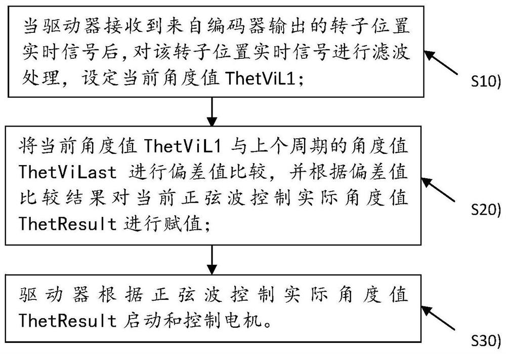
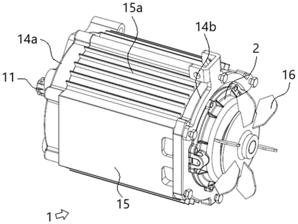
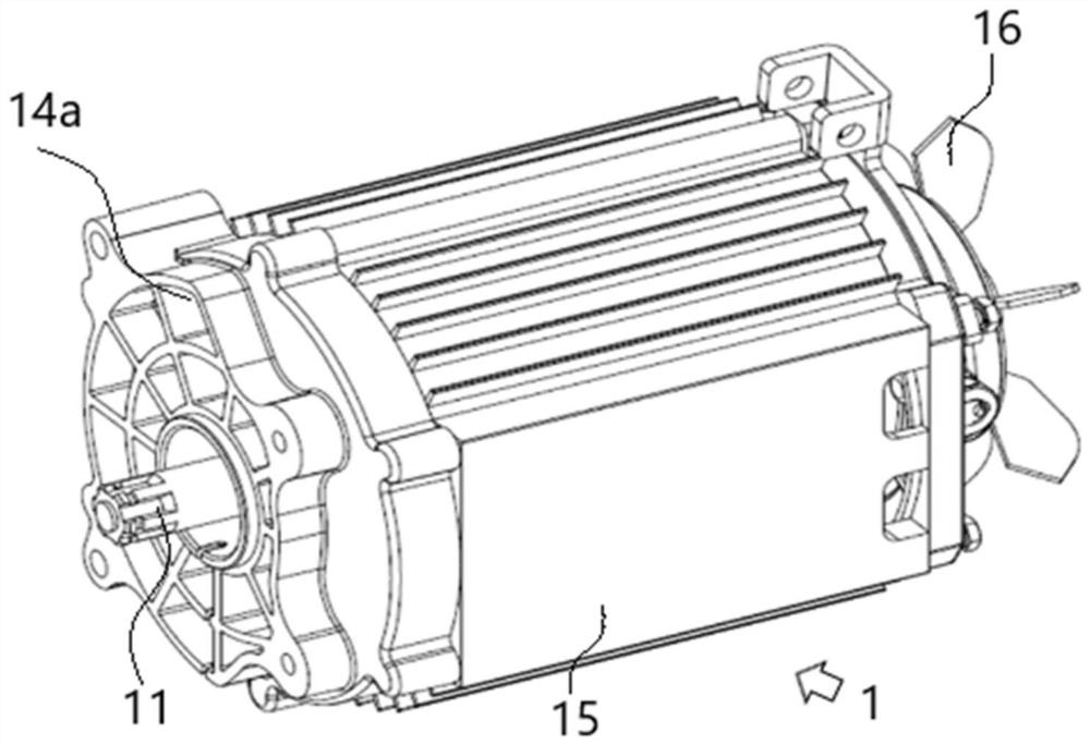
[0044] Embodiment 1: This embodiment proposes a low failure rate tricycle drive system, including a motor 1 on a tricycle frame (using a known tricycle structure) and a driver for controlling the driving operation of the motor 1. The motor 1 includes a motor mounted on the motor The encoder 2 on the shaft 11 can significantly reduce the failure rate; the communication connection between the encoder 2 and the driver, the encoder 2 sends the detected rotor position signal to the driver, and the driver performs sine wave drive control on the motor based on the rotor position signal , can significantly improve the driving precision of the tricycle driving system and realize fine control; see figure 1 As shown, the control steps of the present embodiment include:
[0045] S10), after the driver receives the real-time signal of the rotor position output from the encoder 2, the real-time signal of the rotor position is filtered, and the current angle value ThetViL1 is set;
[0046] ...
Embodiment 2
[0057] Embodiment 2: On the basis of the tricycle drive system proposed in Embodiment 1, this embodiment 2 further proposes a self-calibration control method for the encoder 2. The encoder 2 uses an inductive position encoder for real-time detection of the rotor position signal; Before motor 1 is used, encoder 2 performs self-calibration control in advance, among which, please refer to Figure 6 As shown, the operation steps of the self-calibration control include:
[0058] A10), power on the motor 1 with the encoder 2 installed, the motor 1 is in a stable state of constant speed rotation by external force, preferably, in this step A10), the range of rotation speed of the motor 1 is set to its normal driving time 20-80% of rated speed;
[0059] A20), adjust the original sine-cosine signal located in the inner induction coil of the encoder 2, and adjust the output amplitude of the encoder based on the original sine-cosine signal, so that the encoder 2 can be set to microsecond...
Embodiment 3
[0063] Embodiment 3: On the basis of Embodiment 1 and Embodiment 2, this embodiment further proposes a high-efficiency tricycle drive system, the motor 1 adopts a salient-pole permanent magnet synchronous motor that is beneficial to field-weakening control, and the stator assembly 12 includes a stator core (not shown in the figure) and winding (not shown in the figure), the rotor assembly 13 includes the rotor iron core 13b and the permanent magnetic steel 13a; through the field weakening control to the salient pole permanent magnet synchronous motor, its speed regulation range is improved, and at the same time, the Increase the number of coil turns of a single winding to increase the torque of the salient pole permanent magnet synchronous motor. In this embodiment, the speed regulation range of the salient pole permanent magnet synchronous motor is 0-2000 rpm;
[0064] Preferably, in this embodiment, please refer to Figure 7 , Figure 8 , Figure 9 and Figure 10 As shown...
PUM
| Property | Measurement | Unit |
|---|---|---|
| Thickness | aaaaa | aaaaa |
Abstract
Description
Claims
Application Information
 - R&D
- Intellectual Property
- Life Sciences
- Materials
- Tech Scout
- Unparalleled Data Quality
- Higher Quality Content
- 60% Fewer Hallucinations
Browse by: Latest US Patents, China's latest patents, Technical Efficacy Thesaurus, Application Domain, Technology Topic, Popular Technical Reports.
© 2025 PatSnap. All rights reserved.Legal|Privacy policy|Modern Slavery Act Transparency Statement|Sitemap|About US| Contact US: help@patsnap.com


