Supercharge Your Innovation With Domain-Expert AI Agents!

Welding wire for welding turbine shell waste discharge valve, welding process and welding tool

A welding process and welding tooling technology, used in welding media, welding accessories, welding equipment, etc., can solve problems such as shrinkage, welding hot cracks, and lack of penetration between layers, and achieve short time required and no cracks in welding quality. , The effect of good internal welding quality

Pending Publication Date: 2020-12-18
江阴机械制造有限公司
View PDF0 Cites 0 Cited by
  • Summary
  • Abstract
  • Description
  • Claims
  • Application Information

AI Technical Summary

Problems solved by technology

[0007] In order to solve the problems existing in the prior art, the present invention provides a welding wire, a welding process and a welding tool for the welding of the exhaust valve of the turbine shell, so as to solve the welding thermal cracks caused by the welding of dissimilar steel materials. The process solves defects such as incomplete penetration between layers, shrinkage porosity, and pores to obtain better internal welding quality. The technical scheme is as follows:

Method used


Image

  • Welding wire for welding turbine shell waste discharge valve, welding process and welding tool
  • Welding wire for welding turbine shell waste discharge valve, welding process and welding tool
  • Welding wire for welding turbine shell waste discharge valve, welding process and welding tool

Examples


Embodiment 1

[0091] In the preferred embodiment provided by the present invention, the composition and weight percentage of the welding wire (abbreviated as the first welding wire) for welding the exhaust valve of the turbine casing are:

[0092] C: 0-0.22%;

[0093] Mn: 0-0.1%;

[0094] Fe: 0-9.7%;

[0095] P: 0-0.003%;

[0096] S: 0-0.002%;

[0097] Si: 0-0.2%;

[0098] Ti: 0-0.11%;

[0099] Cr: 18-24.6%;

[0100] AL: 0-2.15%;

[0101] Zr: 0-0.05%;

[0102] The remainder is Ni.

Embodiment 2

[0104] In another embodiment provided by the present invention, the composition and weight percentage of the welding wire (second welding wire for short) used for welding the exhaust valve of the turbine casing are:

[0105] C: 0-0.05%;

[0106] Mn: 2.5-3.5%;

[0107] Fe: 0-1.5%;

[0108] P: 0-0.01%;

[0109] S: 0-0.010%;

[0110] Si: 0-0.25%;

[0111] Cu: 0-0.5%;

[0112] Ti: 0-0.75%;

[0113] Cr: 18-22%;

[0114] Nb and Ta: 2.0-3.0%;

[0115] The remainder is Ni.


PUM

PropertyMeasurementUnit
Diameteraaaaaaaaaa
Melting pointaaaaaaaaaa

Abstract

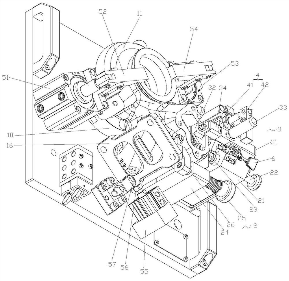
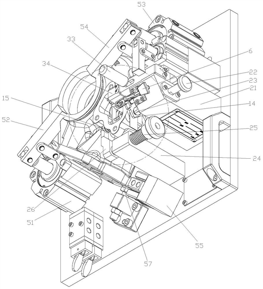
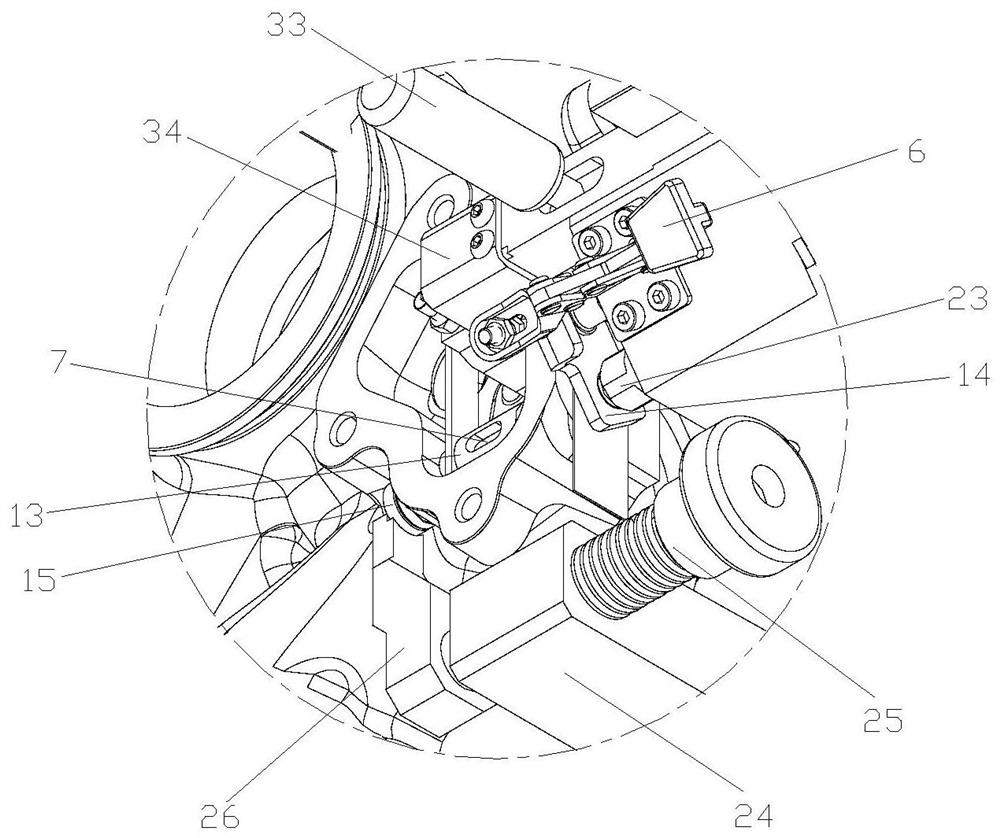
The invention discloses a welding wire for welding a turbine shell waste discharge valve, a welding process and a welding tool. The welding process comprises the following steps of preparing welding wires; selecting welding equipment; setting welding parameters; a welding path, specifically, starting pulse self-fusion welding at the center of a to-be-welded part to perform arcing heating, performing pulse self-fusion welding from the center of the to-be-welded part to the first end part of the to-be-welded part, performing pulse wire feeding welding from the first end part to the second end part of the to-be-welded part, and only performing pulse self-fusion welding without wire feeding when returning from the second end part to the first end part, and then performing reciprocating weldingbetween the first end part and the second end part, wherein the center of the to-be-welded part is located on a stellite vertical shaft, and the first end part and the second end part are the left end and the right end of the to-be-welded part, and finally performing arc extinguishing; and naturally cooling after arc extinguishing is finished. According to the welding wire for welding the turbineshell waste discharge valve, the crack defect of carbide precipitation is overcome; and the multi-layer and multi-pass welding process overcomes the defects of incomplete penetration, shrinkage porosity, air holes and the like between layers, a tool is pneumatically welded, and the welding quality and the production efficiency are improved.

Description

technical field [0001] The invention relates to the field of turbine shell welding, in particular to a welding wire for welding a waste discharge valve of a turbine shell, a welding process and a welding tool. Background technique [0002] The exhaust gas recirculation system of the turbocharger is used in the engine of the heavy-duty truck, and the biggest test it faces in the work is high temperature and fatigue. The working temperature of the turbocharger is generally 600-650°C, while the turbine using AVG technology will generate a high temperature of 1000°C. The high-temperature exhaust gas discharged from each stroke of the engine is introduced into the turbocharger casing, and after driving the internal impeller to work, it is discharged through the waste gas valve and the gas outlet of the volute. Due to the temperature changes of the engine caused by the acceleration, braking, and deceleration of the vehicle, the main failure forms of the turbo exhaust valve are hi...

Claims


Application Information

Patent Timeline
IPC IPC(8): B23K35/30B23K9/133B23K9/16B23K9/32B23K35/02
CPCB23K35/304B23K9/133B23K9/16B23K9/32B23K35/0261
Inventor 曹艳
Owner 江阴机械制造有限公司
Features
  • R&D
  • Intellectual Property
  • Life Sciences
  • Materials
  • Tech Scout
  • Unparalleled Data Quality
  • Higher Quality Content
  • 60% Fewer Hallucinations
Learn More