Vertical grinding-turning compound machine tool

A compound machine tool and vertical grinding technology, applied in the field of machine tools, can solve the problems of failing to meet the requirements of machining accuracy, affecting machining efficiency and machining accuracy, and limited workpiece grinding accuracy, reducing turnover, improving machining efficiency, and high positioning. The effect of accuracy and repeatability

Pending Publication Date: 2020-12-18
天津林凯数控机床有限公司
View PDF10 Cites 0 Cited by
  • Summary
  • Abstract
  • Description
  • Claims
  • Application Information

AI Technical Summary

Problems solved by technology

The existing processing methods commonly used are: turning is completed on an ordinary or CNC lathe, and grinding is processed on a grinding machine. This processing method requires secondary clamping, which will affect processing efficiency and processing accuracy.
In order to improve the processing efficiency, some processing enterprises adopt the method of adding a grinding spindle on the basis of the structure of the vertical lathe, so that the workpiece can be clamped at one time, which can improve the processing efficiency, but affected by the accuracy of the lathe, the grinding of the workpiece The accuracy is limited, and for some parts with high precision requirements, the machining accuracy requirements cannot be met

Method used


Image

  • Vertical grinding-turning compound machine tool
  • Vertical grinding-turning compound machine tool
  • Vertical grinding-turning compound machine tool

Examples


Embodiment Construction

[0037] The present invention will be described in further detail below in conjunction with the drawings and specific examples. The following examples are only descriptive, not restrictive, and cannot limit the protection scope of the present invention.

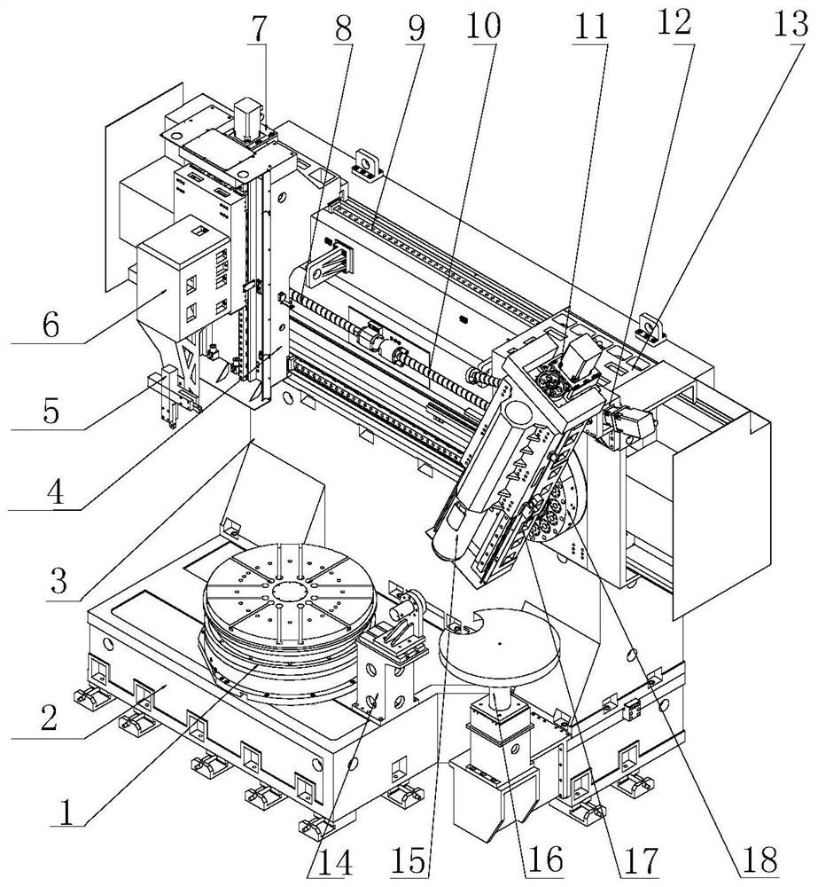
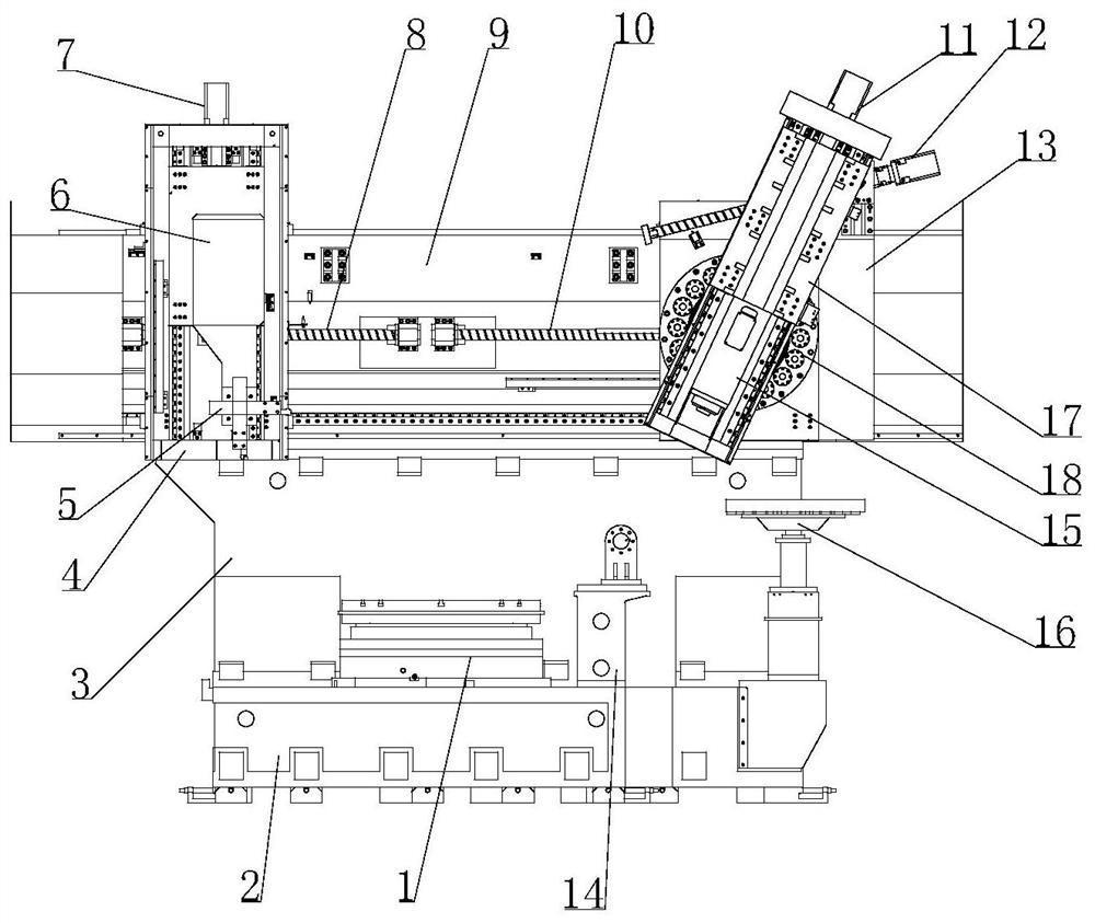
[0038] A kind of vertical grinding and turning compound machine tool, please refer to Figure 1-11 , mainly including bed 2, column 3, beam 9, workbench mechanism 1, turning bed saddle 4, turning tool holder mechanism 6, turning tool handle 5, turning X-axis transmission mechanism 8, turning Z-axis transmission mechanism 7, grinding Cutting saddle 13, grinding main shaft mechanism 15, sliding seat 17, grinding X-axis transmission mechanism 10, grinding B-axis swing angle driving mechanism 12, grinding Z-axis transmission mechanism 11, turntable locking mechanism 18.

[0039] The bed, the column and the beam constitute the main structure of the machine tool, the column is fixed on the bed, and the beam is fixed on the column. ...


PUM


Abstract

The invention relates to a vertical grinding-turning compound machine tool. The vertical grinding-turning compound machine tool is characterized in that a stand column is fixed to a machine tool body,and a cross beam is fixed to the stand column; a turning saddle is connected with the cross beam through a horizontal linear guide rail and is driven by a turning X-axis drive mechanism; a turning tool rest mechanism is connected with the turning saddle through a vertical linear guide rail and is driven by a turning Z-axis drive mechanism; a turning tool shank is arranged below the turning tool rest mechanism; a grinding saddle is connected with the cross beam through a horizontal linear guide rail and is driven by a grinding X-axis drive mechanism; a grinding spindle mechanism is connected with a sliding seat through a linear guide rail and is driven by a grinding Z-axis drive mechanism; a rotating disc type locking mechanism is connected between the middle of the sliding seat and the grinding saddle, the center of the rotating disc type locking mechanism is a B-axis rotating center for swinging of the sliding seat, and a grinding B-axis swing angle driving mechanism is connected between the upper end part of the sliding seat and the grinding saddle. The machine tool achieves one-time workpiece clamping, improves the machining efficiency and guarantees the workpiece precision.

Description

technical field [0001] The invention belongs to the technical field of machine tools, and in particular relates to a vertical grinding and turning compound machine tool. Background technique [0002] Disc, ring and sleeve parts are common part structures in mechanical equipment. These parts are usually processed by turning first, and then precision grinding. The existing processing methods usually adopted are: turning is completed on an ordinary or numerically controlled lathe, and grinding is processed on a grinding machine. This processing method requires secondary clamping, which will affect processing efficiency and processing accuracy. In order to improve the processing efficiency, some processing enterprises adopt the method of adding a grinding spindle on the basis of the structure of the vertical lathe, so that the workpiece can be clamped at one time, which can improve the processing efficiency, but affected by the accuracy of the lathe, the grinding of the workpiec...

Claims


Application Information

Patent Timeline
Patent Type & Authority Applications(China)
IPC IPC(8): B23P23/04
CPCB23P23/04
Inventor 付耀华张志永陈奂林潘盛梁
Owner 天津林凯数控机床有限公司
Why Eureka
Try Eureka