A Hydraulic Casing Centralizer Used in Oil Exploitation

It is a hydraulic technology for oil exploitation, which is applied in the direction of casing, drill pipe, earthwork drilling, etc. It can solve problems such as difficult fixing, casing eccentricity in the horizontal section, poor centering, and insufficient bearing capacity, etc., to achieve fastening, fastening, The effect of high safety and strong plasticity

Active Publication Date: 2021-01-29
胜利油田固邦石油装备有限责任公司
View PDF1 Cites 0 Cited by
  • Summary
  • Abstract
  • Description
  • Claims
  • Application Information

AI Technical Summary

Problems solved by technology

[0002] Casing cementing and perforating completion is one of the important methods for horizontal well completion. However, at present, there are problems in horizontal well cementing such as eccentric casing in the horizontal section, poor centering, and uneven thickness of the cement sheath formed after cementing, which is a serious problem. It affects the cementing quality of horizontal wells and the performance of the productivity advantages of horizontal wells
At present, the most effective way to improve the cementing quality of horizontal wells is to add a rigid centralizer to the casing in the horizontal section, but conventional rigid centralizers have the following disadvantages: the outer diameter is large, and the casing is difficult to run in; wall, forming sand plugging; insufficient bearing capacity, poor quality of casing centering
[0004] 1. The existing hydraulic casing centralizers used for oil production make it difficult to fix the casing in well holes of different sizes during use;
[0005] 2. During the use of the existing hydraulic casing centralizers used in oil exploitation, the casing is usually stuck and fastened, that is, rigidly fixed, which is easy to cause certain damage to the casing and other mechanisms

Method used


Image

  • A Hydraulic Casing Centralizer Used in Oil Exploitation
  • A Hydraulic Casing Centralizer Used in Oil Exploitation
  • A Hydraulic Casing Centralizer Used in Oil Exploitation

Examples


Embodiment Construction

[0032] The following will clearly and completely describe the technical solutions in the embodiments of the present invention with reference to the accompanying drawings in the embodiments of the present invention. Obviously, the described embodiments are only some, not all, embodiments of the present invention. Based on the embodiments of the present invention, all other embodiments obtained by persons of ordinary skill in the art without making creative efforts belong to the protection scope of the present invention.

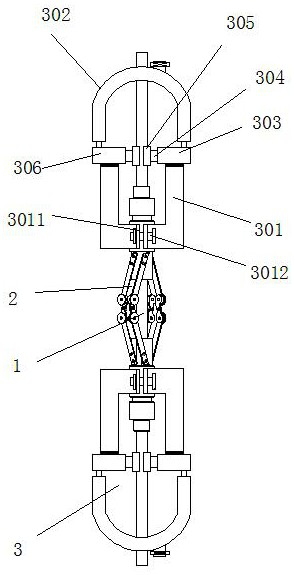
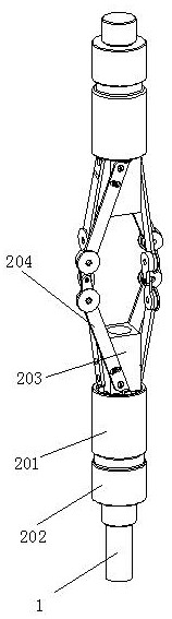
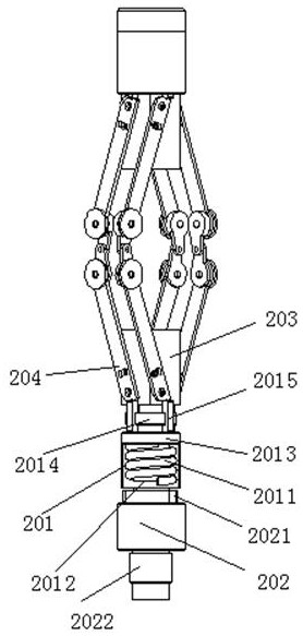
[0033] see Figure 1-7, in an embodiment of the present invention, a hydraulic casing centralizer for oil production, including a casing 1, a wellbore fastening expander 2 and a double linkage centralizing mechanism 3, the casing 1 is fastened along the wellbore The vertical axis of the expander 2 is inserted into the wellbore tightening expander 2, and the two ends of the casing 1 and the wellbore tightening expander 2 are respectively provided with a double-...


PUM


Abstract

The invention discloses a hydraulic casing centralizer for petroleum exploitation, which belongs to the technical field of petroleum completion engineering and comprises a casing, a wellbore fastening expander and a double linkage centralizing mechanism. The casing is tightened along the wellbore The vertical axis of the solid expander is inserted into the wellbore fastening expander. The two ends of the casing and the wellbore fastening expander are respectively provided with double-linkage centralizing mechanisms. The two double-linkage centralizing mechanisms are vertically The direction is symmetrical with respect to the center line of the horizontal direction of the borehole fastening expander. The casing is fixed in the wellbore and the position of the casing is realized through the borehole fastening expander, and the flexible centralization of the casing is realized through the double linkage centralization mechanism. Fixing, that is, the double-linkage righting mechanism in the present invention realizes the flexible righting and fixing of the casing through the combination of air pressure and hydraulic pressure, so that the casing has strong plasticity and quick response during use, and it is safe for casing and other oil well construction equipment. Play a certain degree of flexible protection.

Description

technical field [0001] The invention belongs to the technical field of petroleum well completion engineering, in particular to a hydraulic casing centralizer for petroleum exploitation. Background technique [0002] Casing cementing and perforating completion is one of the important methods for horizontal well completion. However, at present, horizontal well cementing has the problems of casing eccentricity and poor centering in the horizontal section, and uneven thickness of the cement sheath formed after cementing, which is a serious problem. It affects the cementing quality of the horizontal well and the performance of the productivity advantage of the horizontal well. At present, the most effective way to improve the cementing quality of horizontal wells is to add a rigid centralizer to the casing in the horizontal section, but conventional rigid centralizers have the following disadvantages: the outer diameter is large, and it is difficult to run the casing; wall, form...

Claims


Application Information

Patent Timeline
Patent Type & Authority Patents(China)
IPC IPC(8): E21B17/10
CPCE21B17/1021E21B17/1078
Inventor 王伟伟徐希周韩吉森于波宋艳芳管明明
Owner 胜利油田固邦石油装备有限责任公司
Why Eureka
Try Eureka