Supercharge Your Innovation With Domain-Expert AI Agents!

Electric push rod with hand-rotating release device

A release device, electric push rod technology, applied in the direction of electromechanical devices, electric components, transmission devices, etc., can solve the problems of limited installation stroke, complicated operation, difficult to control the pulling force or stroke, etc., to achieve convenient operation and smoothness. Good, reduce the effect of momentary oversize

Pending Publication Date: 2020-12-18
ZHEJIANG JIECHANG LINEAR MOTION TECH
View PDF2 Cites 5 Cited by
  • Summary
  • Abstract
  • Description
  • Claims
  • Application Information

AI Technical Summary

Problems solved by technology

[0005] On the current existing electric push rods, usually only a clutch device is provided, or only a self-locking device is provided, even if the clutch device and the self-locking device are provided at the same time, the drive components that drive these two devices are usually separated from each other, that is, When the operator needs to control the clutch device and the self-locking device at the same time, the two devices need to be operated independently, so the operation will appear more complicated
[0006] In addition, the current clutch device or self-locking device, which drives the clutch device or self-locking device, basically relies on the pull wire to pull the pull rod. In this mode of operation, it is difficult to control the pulling force or stroke, which leads to the failure of the clutch device or self-locking device. Not very smooth when running
Of course, there are also release devices similar to hand rotation on the market. For example, the Chinese utility model patent CN201220326831. The installation stroke of the electric push rod is relatively limited, and the installation space of this kind of electric push rod with hand-rotating device will be affected

Method used


Image

  • Electric push rod with hand-rotating release device
  • Electric push rod with hand-rotating release device
  • Electric push rod with hand-rotating release device

Examples


Embodiment 1

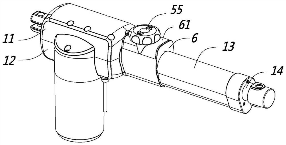
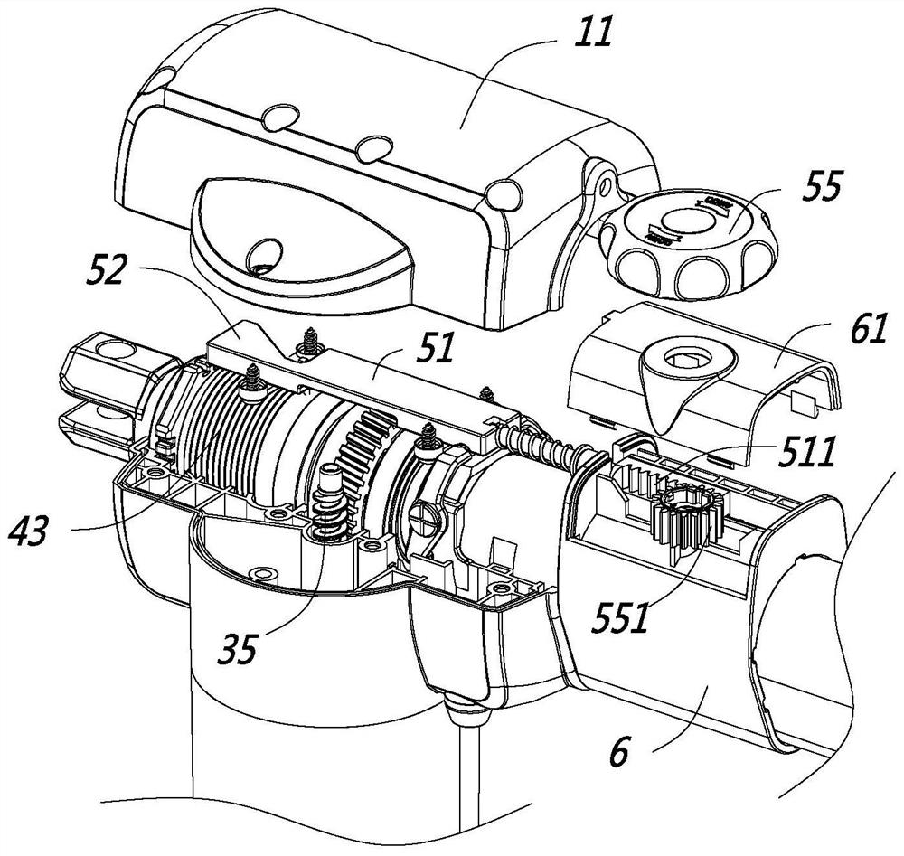
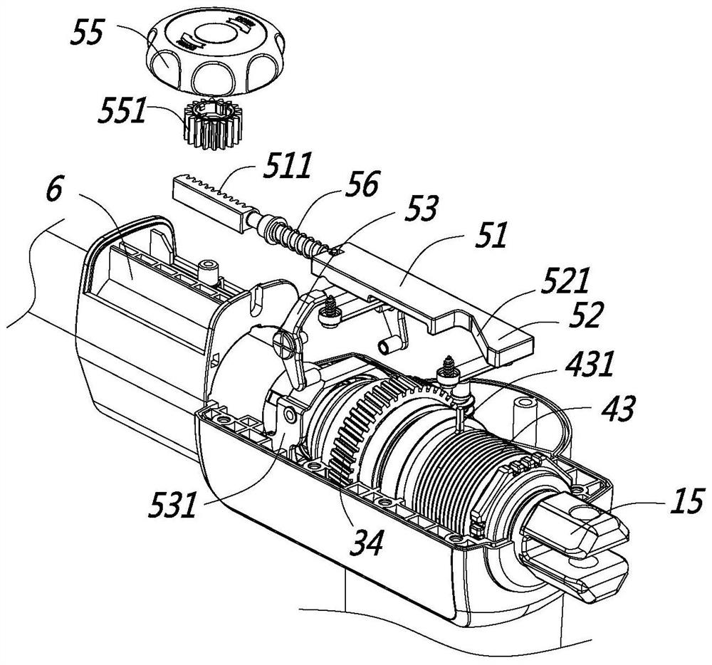
[0039] like Figure 1 to Figure 5 As shown, this embodiment is an electric push rod. The electric push rod is also commonly called a linear drive or a linear actuator. The electric push rod includes a casing, an outer tube 13, an inner tube 14, a drive motor, a transmission assembly, and a rotating screw. 20 and a transmission nut 21, the drive motor drives the rotating screw 20 to rotate through the transmission assembly, the rotating screw 20 rotates and drives the transmission nut 21 to move axially along the rotating screw 20, the transmission nut 21 is fixedly connected with the inner tube 14, and the transmission nut 21 When moving axially, the inner tube 14 is driven to move axially relative to the outer tube 13 and the outer shell, and the outer end of the inner tube 14 is connected to the object to be driven. The electric push rod in this embodiment also includes:

[0040]The clutch device is arranged between the transmission assembly and the rotating screw 20, and is...


PUM


Abstract

The invention discloses an electric push rod with a hand-rotating release device, and belongs to the technical field of linear transmission. The electric push rod comprises a shell, a driving motor, atransmission assembly, a rotating screw rod and a transmission nut, and further comprises a clutch device, a self-locking device and the hand-rotating release device, wherein the clutch device is used for connecting or disconnecting power transmission between the transmission assembly and the rotating screw rod; the self-locking device generates frictional resistance on the rotating lead screw when the rotating lead screw rotates reversely; and the hand-rotating release device comprises a release rotary knob, a first driving component is connected with the clutch device, a second driving component is used for being connected with the self-locking device, the release rotary knob is in an initial state and a complete release state through rotating motion, and in the process from the initialstate to the complete release state, the first driving component drives the clutch device to break power connection, and the second driving component drives a release torsion spring to be released. The electric push rod has the advantages that the hand-rotating release device can control two devices, and thus the operation is smoother and more convenient.

Description

【Technical field】 [0001] The invention relates to an electric push rod with a hand-rotating release device, belonging to the technical field of linear transmission. 【Background technique】 [0002] Electric push rod, also known as linear actuator, is widely used in furniture, medical equipment, solar power generation and other fields. Its main structure includes drive motor, transmission worm, worm wheel, screw, nut. The working principle is that the drive motor drives the transmission worm to rotate. The transmission worm is engaged with the worm wheel to drive the worm wheel to rotate, the rotation of the worm wheel drives the rotation of the screw, and the rotation of the screw drives the nut to move axially. [0003] Combined with the application environment of the electric push rod, when the electric push rod encounters a failure of the drive motor, or in the event of a power failure or other situations where the power needs to be cut off, a clutch device will be added, ...

Claims


Application Information

Patent Timeline
IPC IPC(8): F16H37/12F16H25/20F16H25/24F16D49/08H02K7/06H02K7/10H02K7/116
CPCF16H37/124F16H25/2025F16H25/2454F16D49/08H02K7/06H02K7/10H02K7/116F16H2025/2065F16H2025/2071F16H2025/209F16H2025/2463F16D2127/04F16D2121/24F16D2125/60F16D65/14H02K7/108F16H2025/2084F16H2025/2031H02K7/1166
Inventor 许欣赵新星
Owner ZHEJIANG JIECHANG LINEAR MOTION TECH
Features
  • R&D
  • Intellectual Property
  • Life Sciences
  • Materials
  • Tech Scout
  • Unparalleled Data Quality
  • Higher Quality Content
  • 60% Fewer Hallucinations
Learn More