
Chip, chip set, electrical parameter detection method, consumables and image forming device

A chipset and chip technology, applied in the field of image processing, can solve the problems of different main frequencies, signal conflicts, inconvenient detection operations, etc.

Active Publication Date: 2020-12-18
ZHUHAI PANTUM ELECTRONICS
View PDF5 Cites 6 Cited by
  • Summary
  • Abstract
  • Description
  • Claims
  • Application Information

AI Technical Summary

Problems solved by technology

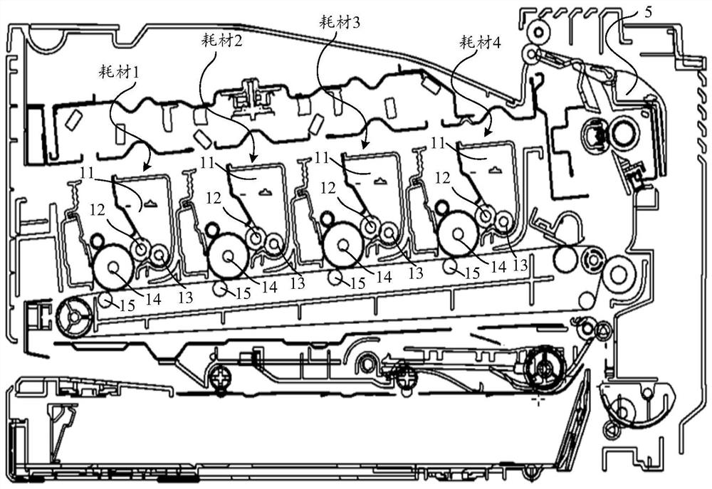
[0004] However, the inventor found in the process of realizing the present invention that since there are usually multiple (generally 4) consumables of the image forming device, if simply controlling multiple consumables The chip outputs a low level at a certain time interval for detection. When multiple chips are powered on, due to the different power-on initialization times of the chips or the different main frequencies of the chips, signal conflicts may occur, that is, the image forming device may simultaneously Received low-level output from multiple chips, so it is not ready to identify which consumable chip the low-level signal comes from, and it is not easy to perform detection operations

Method used


Image

  • Chip, chip set, electrical parameter detection method, consumables and image forming device
  • Chip, chip set, electrical parameter detection method, consumables and image forming device
  • Chip, chip set, electrical parameter detection method, consumables and image forming device

Examples


Embodiment Construction

[0118] In order to better understand the technical solutions of the present invention, the embodiments of the present application will be described in detail below in conjunction with the accompanying drawings.

[0119] It should be understood that the described embodiments are only some, but not all, embodiments of the present invention. Based on the embodiments of the present invention, all other embodiments obtained by those of ordinary skill in the art without creative efforts shall fall within the protection scope of the present invention.

[0120] In this application, "at least one" means one or more, and "plurality" means two or more. "And / or" describes the association relationship of associated objects, indicating that there may be three types of relationships, for example, A and / or B, which can mean: A exists alone, A and B exist simultaneously, and B exists alone, where A, B can be singular or plural. The character " / " generally indicates that the associated object...


PUM


Abstract

The embodiment of the invention provides a chip, a chip set, an electrical parameter detection method, consumables and an image forming device. The chip is detachably installed on the consumables, theconsumables and at least one first consumable are detachably installed on the same image forming device, each first consumable is provided with a first chip, the image forming device includes a mounting detection pin, the chip and the first chip are electrically connected with the mounting detection pin through the same communication bus, and the chip includes a mounting detection terminal configured to be electrically connected with the mounting detection pin of the image forming device through the communication bus, and a chip control unit configured to control the mounting detection terminal to output a low level after the chip is powered on, so that a current loop is formed between the chip and the image forming device, and the time for forming the current loop between the chip and the image forming device is different from the time for forming the current loop between the first chip and the image forming device. When whether the plurality of chips are in good contact with the image forming device is detected, the plurality of chips do not generate a signal conflict problem.

Description

technical field [0001] The present application relates to the technical field of image processing, and specifically relates to a chip, a chip set, an electrical parameter detection method, consumables, and an image forming device. Background technique [0002] Image forming apparatus (Image forming apparatus), as a kind of computer peripheral equipment, has been gradually popularized in offices and homes with the maturity of imaging technology, due to its advantages of fast speed and low cost of single-page imaging. According to different functions, image forming devices include printers, copiers, multi-function machines, etc., and according to different imaging principles, image forming devices include laser printers, inkjet printers, dot matrix printers, etc. [0003] Image forming devices are usually provided with consumables that need to be replaced. Taking a laser printer as an example, the consumables include a process cartridge or a developing cartridge for accommodat...

Claims


Application Information

Patent Timeline
IPC IPC(8): G03G15/08G03G21/18G03G15/00G03G21/16
CPCG03G15/0863G03G21/1875G03G21/1892G03G15/80G03G21/1652G03G21/1867G03G21/1882G03G15/0894G03G21/181G06F3/121G06F3/1279G06F3/12
Inventor 王波李海雄尹爱国
Owner ZHUHAI PANTUM ELECTRONICS
Learn More