
Motor based on pulsating heat pipe

A technology of pulsating heat pipes and casings, applied in the field of motors, can solve the problems of high temperature of stator components, temperature rise, wear of mechanical parts, etc., and achieve the effects of improving cooling efficiency, reducing motor volume, and high heat flux density

Active Publication Date: 2020-12-18
XIAMEN TUNGSTEN
View PDF3 Cites 3 Cited by
  • Summary
  • Abstract
  • Description
  • Claims
  • Application Information

AI Technical Summary

Problems solved by technology

However, there are still the following problems: air cooling and liquid cooling mostly dissipate heat on the casing, resulting in poor cooling inside the motor and high temperature of the stator components inside the motor; Direct contact, the temperature rises, and the temperature difference of the winding along the motor axis is large; there is a temperature difference between the internal and external parts of the motor, and the difference in thermal stress may cause wear of the mechanical parts

Method used


Image

  • Motor based on pulsating heat pipe
  • Motor based on pulsating heat pipe
  • Motor based on pulsating heat pipe

Examples


Embodiment Construction

[0024] The present invention will be further described below in conjunction with the accompanying drawings and specific embodiments.

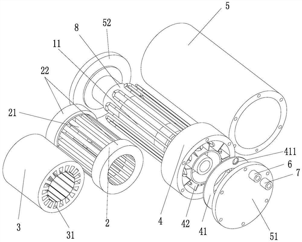
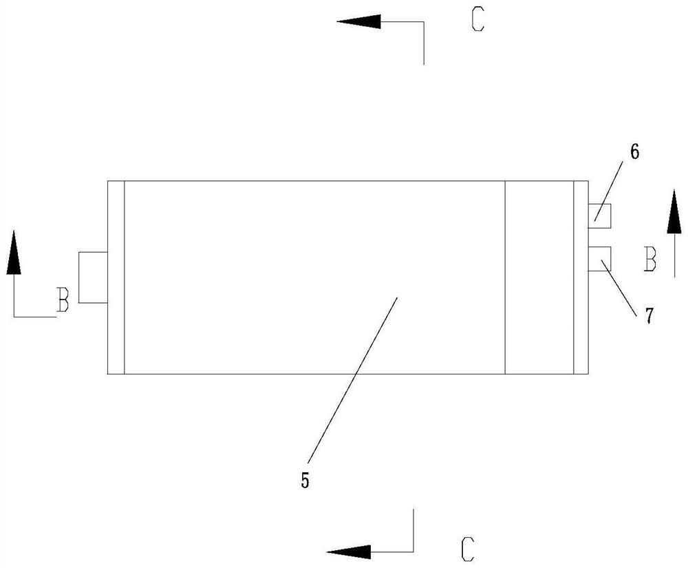
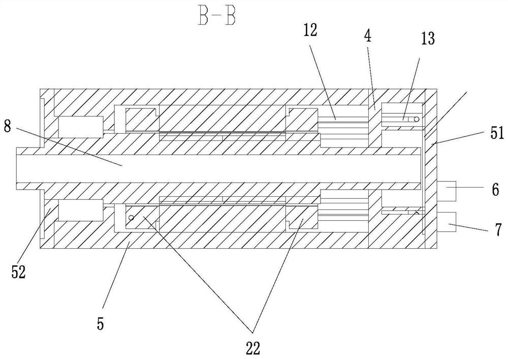
[0025] Please refer to Figure 1 to Figure 5 , the present invention provides a motor based on a pulsating heat pipe, comprising a stator winding 2, a stator core 3, and a central shaft 8, wherein the stator winding 2, the stator core 3, and the central shaft 8 are coaxially arranged; the stator core 3 is arranged along its diameter There are a plurality of stator slots 31 for placing windings; it also includes a pulsating heat pipe 1, and the pulsating heat pipe 1 includes a condensation section 13 and an evaporation section 11; in the radial direction of the stator core 3, the pulsating heat pipe 1 in the stator slot 31 The evaporation section 11 is located between the bottom of the stator slot 31 and an effective edge 21 of the stator winding 2 .

[0026] Herein, "effective side" refers to the straight part of the stator winding embedded in...


PUM


Abstract

The invention provides a motor based on a pulsating heat pipe. The motor comprises a distributed stator winding, a stator core, a central shaft and the pulsating heat pipe. The stator winding, the stator core and the central shaft are coaxially arranged; the stator core is provided with a plurality of stator grooves used for placing windings; the pulsating heat pipe comprises a condensation section and an evaporation section; and in a radial direction of the stator, an evaporation section of the pulsating heat pipe in the stator groove is located between the bottom of the stator groove and oneeffective edge of the stator winding. According to the technical scheme, a winding is directly cooled through the pulsating heat pipe, the temperature of the stator assembly is reduced, and motor cooling efficiency is improved.

Description

technical field [0001] The invention relates to the field of motors, and specifically refers to a motor based on a pulsating heat pipe. Background technique [0002] The motor will generate heat during the working process, and the overheating of the motor will bring a series of problems. Excessive stator winding temperature can cause insulation failure and eventually burn out the motor. If the temperature is too high, the lubrication inside the bearing will be reduced, resulting in shortened bearing life, and it will also damage the strength of the rotating shaft, resulting in large radial expansion. This requires that a good cooling effect must be ensured during the long-term operation of the motor. At present, the cooling methods of motors are mostly air-cooled and liquid-cooled, which can control the temperature rise of the motor within a certain range. However, there are still the following problems: air cooling and liquid cooling mostly dissipate heat on the casing, ...

Claims


Application Information

Patent Timeline
IPC IPC(8): H02K9/20H02K1/20H02K3/24
CPCH02K9/20H02K1/20H02K3/24Y02T10/64
Inventor 牟纳斯邓栓陈秉垚蔡锋宾刘伟
Owner XIAMEN TUNGSTEN
Learn More