
A concrete block cutting machine with waste removal mechanism

A concrete block and waste removal technology, applied in the field of block processing, can solve the problems of large damage to steel wire, trouble, and insufficient cutting effect, and achieve the effect of good cutting effect, small damage, and rapid cooling

Active Publication Date: 2022-01-11
巢湖市永安新型建材有限责任公司
View PDF0 Cites 0 Cited by
  • Summary
  • Abstract
  • Description
  • Claims
  • Application Information

AI Technical Summary

Problems solved by technology

[0003] In the processing of concrete blocks, it is necessary to shape the raw material into a green body first, and then cut the green body. In the prior art, the general cutting machine adopts wire cutting, and the specific principle is to directly use the lifting device to push the intersecting steel wires. Press on the green body for cutting. In this cutting process, the vertical force of the steel wire acts on the green body completely, and the cutting effect is not good enough. Once a relatively hard green body is encountered, the damage to the steel wire is greater, and the cutting Finally, waste materials are easy to come out on both sides of the green body. In the prior art, it is generally manually pushed, and the waste materials on both sides are pushed down and dropped into the waste groove under the cutting machine, which is troublesome. Therefore, the present invention proposes a Mechanism's concrete block cutting machine to solve the problems existing in the prior art

Method used


Image

  • A concrete block cutting machine with waste removal mechanism
  • A concrete block cutting machine with waste removal mechanism
  • A concrete block cutting machine with waste removal mechanism

Examples


Embodiment Construction

[0017] In order to deepen the understanding of the present invention, the present invention will be further described below in conjunction with the examples, which are only used to explain the present invention, and do not constitute a limitation to the protection scope of the present invention.

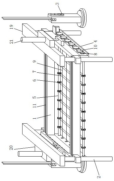
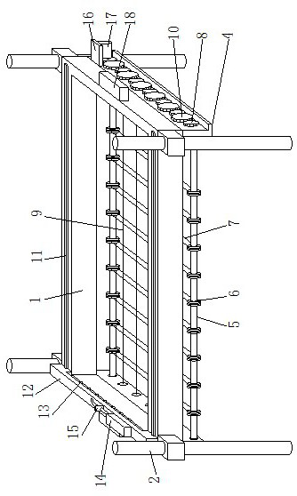
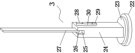
[0018] according to figure 1 , 2 As shown in . 1 is movably installed on the sliding rod 2 through a sliding sleeve, pusher components 3 are provided on both sides of the mounting frame 1, and mounting plates 4 are provided on both sides of the bottom of the mounting frame 1, and the two groups of The front and rear ends between the mounting plates 4 are all rotatably equipped with a rotating shaft 5, the rotating shaft 5 is provided with wire wheels 6, and the wire wheels 6 are equidistantly provided with multiple groups, and the adjacent front and rear ends are all wound with wire wheels 6 First cutting wire 7, first gears 8 are arranged on the outside of two groups of mounting p...


PUM


Abstract

The invention provides a concrete block cutting machine with a waste material removal mechanism, which includes a mounting frame, a sliding rod and a pushing assembly. Both sides of the mounting frame are provided with pushing components, both sides of the bottom of the mounting frame are provided with mounting plates, and the front and rear ends between the two groups of mounting plates are rotated and installed with rotating shafts. There are wire wheels on the top, and multiple sets of wire wheels are equidistant; the invention drives the rotation of the wire wheels through the rotation of the rotating shaft, so that the first cutting wire rotates, cuts the blank forward and backward, and drives the second cutting wire through the rotation of the first gear. Self-rotating, cutting the billet left and right. During the cutting process, in addition to the vertical downward cutting force driven by the pneumatic cylinder, the first cutting wire and the second cutting wire also have a rotating cutting force, the cutting effect is better, and the hardness can be cut Higher, less wire damage.

Description

technical field [0001] The invention relates to the technical field of block processing, in particular to a concrete block cutting machine with a waste removal mechanism. Background technique [0002] Autoclaved aerated concrete blocks are made of fly ash, lime, cement, gypsum, slag, etc. A porous concrete product made by steam curing and other processes. [0003] In the processing of concrete blocks, it is necessary to shape the raw material into a green body first, and then cut the green body. In the prior art, the general cutting machine adopts wire cutting, and the specific principle is to directly use the lifting device to push the intersecting steel wires. Press on the green body for cutting. In this cutting process, the vertical force of the steel wire acts on the green body completely, and the cutting effect is not good enough. Once a relatively hard green body is encountered, the damage to the steel wire is greater, and the cutting Finally, waste materials are eas...

Claims


Application Information

Patent Timeline
Patent Type & Authority Patents(China)
IPC IPC(8): B28B11/14B28B17/00
CPCB28B11/145B28B17/0036B28B17/00
Inventor 倪昆
Owner 巢湖市永安新型建材有限责任公司
Learn More