Composite pipe type connection joint
A technology for connecting joints and composite materials, applied in the direction of pipe/pipe joint/pipe fitting, sealing surface connection, passing element, etc., can solve the problems of easy detachment of pipe type and insufficient joint connection, so as to improve the connection stability and avoid detachment. Effect
- Summary
- Abstract
- Description
- Claims
- Application Information
AI Technical Summary
Problems solved by technology
Method used
Image
Examples
Embodiment 1
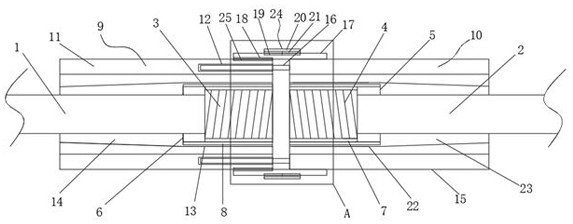
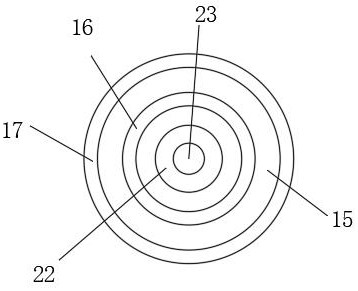
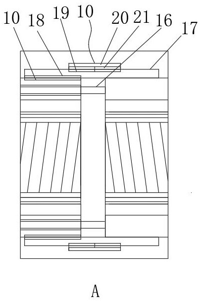
[0022] Embodiment one, by figure 1 , figure 2 with image 3 Given, the present invention includes a composite pipe cylinder one 1 and a composite pipe cylinder two 2, the composite pipe cylinder one 1 and the composite pipe cylinder two 2 both adopt carbon fiber composite material tubes, and one end of the composite pipe cylinder one 1 is provided with Threaded joint one 3, one end of the composite pipe cylinder two 2 is provided with a threaded joint two 4 close to the threaded joint one 3, through the design of the threaded joint one 3 and the threaded joint two 4, it is effective for the composite pipe cylinder one 1 and The connection of the composite pipe column 2 provides convenience, the external connection of the threaded joint 24 is connected with the connecting ring 15, and the external connection of the threaded joint 3 is connected with the connecting ring 26, and through the design of the connecting ring 15 and the connecting ring 26, Effectively avoiding the d...
Embodiment 2
[0023] Embodiment two, on the basis of embodiment one, by figure 1 , figure 2 with image 3 Given, the inner wall of connecting ring one 5 is provided with thread one 7 engaged with threaded joint two 4, the inner wall of connecting ring two 6 is provided with thread two 8 engaged with threaded joint one 3, through thread one 7 and thread two The design of 8 provides convenience for the docking of composite pipe cylinder one 1 and composite pipe cylinder two 2 in the later stage.
[0024] Embodiment two, on the basis of embodiment one, by figure 1 , figure 2 with image 3 Given, the connecting mechanism one 9 includes a sleeve one 11, a threaded slot 12, a receiving groove one 13, a card groove one 14 and an external thread 25, the sleeve one 11 is sleeved on the outside of the connecting ring two 6, the sleeve one 11 One end of the sleeve is provided with a threaded slot 12, and the middle position of the sleeve one 11 is provided with a card slot one 14, and one side ...
Embodiment 4
[0025] Embodiment four, on the basis of embodiment three, by figure 1 , figure 2 with image 3 Given, the connecting mechanism 10 includes a sleeve 15, a threaded insert ring 16, an engaging ring 17, an internal thread 18, an external two-way thread 19, a receiving groove 22 and a card groove 23, and the sleeve 15 is sleeved on the connecting ring On the outside of one 5, the middle position of the sleeve two 15 is provided with a card slot two 23, and one side of the two card slot 23 is provided with a receiving groove two 22 sleeved on the outside of the connecting ring one 5, and the connecting ring 17 is fixedly installed on the sleeve The outer wall of the second 15, the inner wall of the connecting ring 17 is provided with the internal thread 18 engaged with the external thread 25, and the end of the sleeve two 15 near the sleeve one 11 is provided with a threaded insert ring 16 threadedly connected with the threaded slot 12. The middle position of the outer wall of t...
PUM
 Abstract
Description
Claims
Application Information
 - R&D
- Intellectual Property
- Life Sciences
- Materials
- Tech Scout
- Unparalleled Data Quality
- Higher Quality Content
- 60% Fewer Hallucinations
Browse by: Latest US Patents, China's latest patents, Technical Efficacy Thesaurus, Application Domain, Technology Topic, Popular Technical Reports.
© 2025 PatSnap. All rights reserved.Legal|Privacy policy|Modern Slavery Act Transparency Statement|Sitemap|About US| Contact US: help@patsnap.com


