Supercharge Your Innovation With Domain-Expert AI Agents!

Multifunctional trigger device

A triggering device and multi-functional technology, applied in instruments, computer control, simulators, etc., can solve the problems of reducing the number of Euler test points, hidden dangers, waste of labor costs, etc., so as to improve operational safety and avoid false triggering problems. , the effect of eliminating occupancy problems

Pending Publication Date: 2020-12-25
BEIJING INSTITUTE OF TECHNOLOGYGY
View PDF0 Cites 0 Cited by
  • Summary
  • Abstract
  • Description
  • Claims
  • Application Information

AI Technical Summary

Problems solved by technology

The traditional probe-type test generally has the following problems: (1) The trigger probe and the detonator are placed in the highly dangerous flammable, explosive or even toxic industrial gas, and it is not convenient for the operator to check when the triggered test device detects abnormality ; (2) When the concentration of combustible and explosive gas is low or the concentration of injected inert gas is high, it is very likely that the ignition head can ignite the gas but cannot reliably ionize the probe at the same time, resulting in ignition signal and test The trigger signal of the device cannot be synchronized; (3) The probe has been connected to the trigger input port of the test instrument during the test triggering process, and the unsafe factor of stray current flowing out of the input port will cause extremely dangerous safety hazards to the operator; (4) The trigger probe generally occupies a test channel in the data acquisition equipment, which reduces the number of Euler test points for multi-physics field coupling information; (5) The test trigger process is mainly to detect the trigger of the test device, which does not need to detonate the explosive device , the probe-type test triggering process requires the cooperation of two workers. One worker needs to go to the dangerous area to artificially ionize the probe, and the other worker needs to monitor whether the test device is triggered synchronously, which wastes labor costs.

Method used


Image

  • Multifunctional trigger device
  • Multifunctional trigger device
  • Multifunctional trigger device

Examples


Embodiment Construction

[0031] In order to make the purpose, technical solutions and advantages of the present disclosure clearer, the present disclosure will be further described in detail below in conjunction with specific embodiments and with reference to the accompanying drawings.

[0032] It should be noted that, unless otherwise defined, the technical terms or scientific terms used in one or more embodiments of the present specification shall have the common meanings understood by those skilled in the art to which the present disclosure belongs. "First", "second" and similar words used in one or more embodiments of this specification do not indicate any order, quantity or importance, but are used to distinguish different components. "Comprising" or "comprising" and similar words mean that the elements or items appearing before the word include the elements or items listed after the word and their equivalents, without excluding other elements or items. Words such as "connected" or "connected" ar...


PUM


Abstract

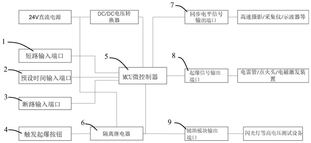
The invention discloses a multifunctional trigger device. The multifunctional trigger device comprises an MCU microcontroller, a first input unit, a detonation signal output port and a synchronous level signal output port, wherein the first input unit, the detonation signal output port and the synchronous level signal output port are electrically connected with the MCU microcontroller. The first output unit sends out a detonation input signal, the MCU microcontroller receives the detonation input signal, a detonation output signal and a synchronous level output signal are generated, the detonation output signal is output from the detonation signal output port, the synchronous level output signal is output from the synchronous level signal output port, an explosion device executes detonation according to the detonation output signal, and a testing device executes testing according to the synchronous level output signal. The probe-free multifunctional trigger device integrates detonationtriggering and testing triggering functions, and is high in safety and stability, capable of saving labor cost and high in man-machine interaction efficiency.

Description

technical field [0001] One or more embodiments of this specification relate to the technical field of explosion test devices, and in particular to a multi-functional trigger device for linkage triggering of multiple equipment in explosion tests. Background technique [0002] Industrial gas detonation, condensed explosive detonation and fragment ultra-high-speed impact loading belong to three typical nonlinear transient dynamic problems. Among them, the air shock wave overpressure and heat radiation characteristics accompanying the gas detonation process can directly reflect its coupling power effect on surrounding objects; the detonation wave velocity, detonation wave pressure, shock wave Physical parameters such as overpressure and the driving scattering speed of the outer metal shell can directly measure the coupling damage effect of the explosive; the initial velocity, velocity attenuation, impact pressure on the target and impact limit velocity of the fragment during ult...

Claims


Application Information

Patent Timeline
IPC IPC(8): G05B19/042
CPCG05B19/0423G05B2219/25257
Inventor 冯治建
Owner BEIJING INSTITUTE OF TECHNOLOGYGY
Features
  • R&D
  • Intellectual Property
  • Life Sciences
  • Materials
  • Tech Scout
  • Unparalleled Data Quality
  • Higher Quality Content
  • 60% Fewer Hallucinations
Learn More