Steel bending equipment for steel machining

A steel and steel technology, applied in the field of steel bending equipment for steel processing, can solve the problems of scratches on the installation contacts, difficulty in moving, and inability to wipe the stains on the outer surface of the steel, so as to achieve the effect of improving smoothness and easy wiping

Inactive Publication Date: 2020-12-29
赵桂荣
View PDF8 Cites 4 Cited by
  • Summary
  • Abstract
  • Description
  • Claims
  • Application Information

AI Technical Summary

Problems solved by technology

[0004] The purpose of the present invention is: in order to solve the problem that no lubricating and rolling structure is installed on the bending device, when the steel is bent, due to the change of the shape of the steel, if the friction force cannot be reduced, the deformation of the steel will When the steel is installed, there will be some scratches or scars on the contact with the steel. There is no structure in the device to facilitate the disassembly and assembly of the steel. After the steel is bent, due to the huge deformation, it will be stuck in the In the installation cavity, it is not easy to move or take out, and it needs to be taken out with additional tools, which is more troublesome. The device is not equipped with any wiping structure, and the stains on the outer surface of the steel cannot be wiped. Steel bending equipment for steel processing

Method used


Image

  • Steel bending equipment for steel machining
  • Steel bending equipment for steel machining
  • Steel bending equipment for steel machining

Examples


Embodiment Construction

[0040] The following will clearly and completely describe the technical solutions in the embodiments of the present invention with reference to the accompanying drawings in the embodiments of the present invention. Obviously, the described embodiments are only some, not all, embodiments of the present invention. Based on the embodiments of the present invention, all other embodiments obtained by persons of ordinary skill in the art without creative efforts fall within the protection scope of the present invention.

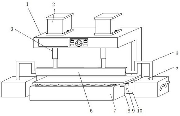
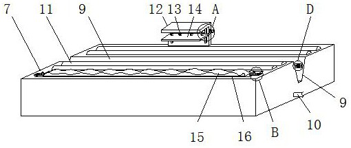
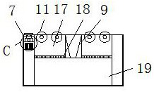
[0041] see Figure 1-8 , the present invention provides a technical solution: a steel bending equipment for steel processing, including a body 1, a lubricating oil tank 5, a base 7, a roller shaft 11, an oil storage box 17, a positioning mechanism 22 and a mounting seat 26, the body 1 is fixedly installed on the base 7 through a side connecting plate, a hydraulic press 2 is fixedly installed on the top of the body 1, and one end of a hydraulic rod 3 installed on th...


PUM


Abstract

The invention discloses steel bending equipment for steel machining, and belongs to the technical field of steel machining. The steel bending equipment comprises a machine body, lubricating oil tanks,a base, roll shafts, an oil storage box, a positioning mechanism and a mounting seat, wherein the machine body is fixedly installed on the base through a side connecting plate, hydraulic machines arefixedly installed at the top of the machine body, and one ends of hydraulic rods installed at the output ends of the hydraulic machines penetrate through and extend to the outer side of the machine body to be fixedly provided with a bending plate. According to the steel bending equipment, the roller shafts are installed on the equipment, when steel is bent and pressure is applied to the bent position of the steel, the roll shafts replace a bent face to make contact with the steel, and when pressure is applied for bending, the steel can be bent along the smooth surfaces of the roll shafts, compared with traditional bending treatment, the situation that the surface of the steel is scratched and damaged is avoided, and meanwhile, the lubricating oil tanks are installed on the outer side of the equipment in a matched mode, the contact positions between the roll shafts and the steel can be effectively lubricated, and the bending smoothness is further improved.

Description

technical field [0001] The invention belongs to the technical field of steel processing, in particular to a steel bending equipment for steel processing. Background technique [0002] Steel is a relatively common metal material. Steel has high hardness and can be used in a wide range of fields. Among them, the steel industry is an important basic industrial sector and the material basis for the development of national economy and national defense construction. The level of the metallurgical industry is also a measure of a country's industrialization. When processing steel, in order to bend the steel at a certain position to form steel parts of different shapes, steel bending equipment is required. [0003] Chinese patent document CN201811436799.3 discloses a steel bending equipment for steel processing, including a base plate, a bearing driving mechanism, a limiting mechanism, a positioning mechanism and a bending mechanism, and the bearing driving mechanism, a limiting mech...

Claims


Application Information

Patent Timeline
IPC IPC(8): B21D5/01B21D37/18B21D43/00B21D43/09B21D45/06B08B1/00
CPCB21D5/01B21D5/002B21D37/18B21D43/003B21D43/09B21D45/06B08B1/143
Inventor 赵桂荣陈婷婷
Owner 赵桂荣
Why Eureka
Try Eureka