Electric spindle system supported by double radial six-pole hybrid magnetic bearings with different magnetic pole surfaces

A hybrid magnetic bearing and axial magnetic bearing technology, which is used in high-precision CNC machine tools, ultra-high-speed, motorized spindle systems, and high-speed fields, can solve the coupling of radial two degrees of freedom and nonlinear increase, and increase the motorized spindle. Volume, increased volume and power consumption, etc., to achieve the effect of low power consumption, simplified design steps, reduced size and power consumption

Inactive Publication Date: 2021-01-01
JIANGSU UNIV
View PDF7 Cites 4 Cited by
  • Summary
  • Abstract
  • Description
  • Claims
  • Application Information

AI Technical Summary

Problems solved by technology

[0004] The Chinese patent application number is CN200810234272, and the document titled "High-speed Electric Spindle System Supported by Five Degrees of Freedom AC Magnetic Bearing" proposes a high-speed electric spindle system supported by an AC / DC three-degree-of-freedom active magnetic bearing and an AC two-degree-of-freedom active magnetic bearing. The structure of the spindle motor, in which the electric spindle uses axial thrust magnetic bearings to provide axial suspension force, requires a larger thrust plate, which will increase the volume of the electric spindle, increase the difficulty of assembly, and limit the increase of the critical speed; the electric spindle adopts For the active three-pole magnetic bearing, the bias flux requires the coil to provide the bias flux, which will increase the volume and power consumption. The use of a three-pole structure will cause the coupling and nonlinearity between the two radial degrees of freedom to increase. for precise control

Method used


Image

  • Electric spindle system supported by double radial six-pole hybrid magnetic bearings with different magnetic pole surfaces
  • Electric spindle system supported by double radial six-pole hybrid magnetic bearings with different magnetic pole surfaces
  • Electric spindle system supported by double radial six-pole hybrid magnetic bearings with different magnetic pole surfaces

Examples


Embodiment Construction

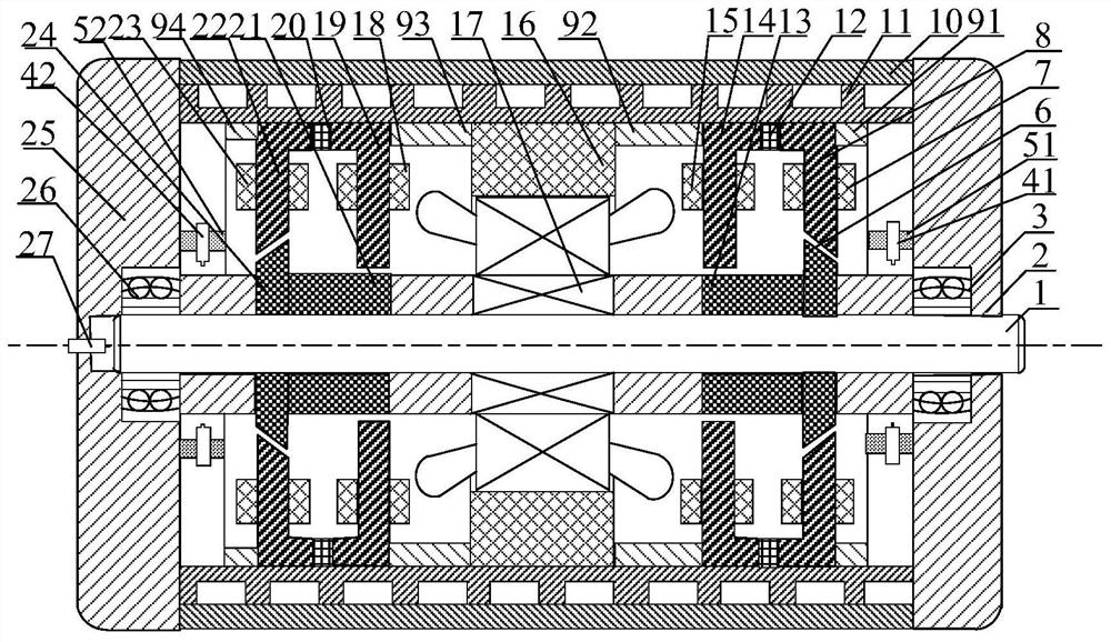
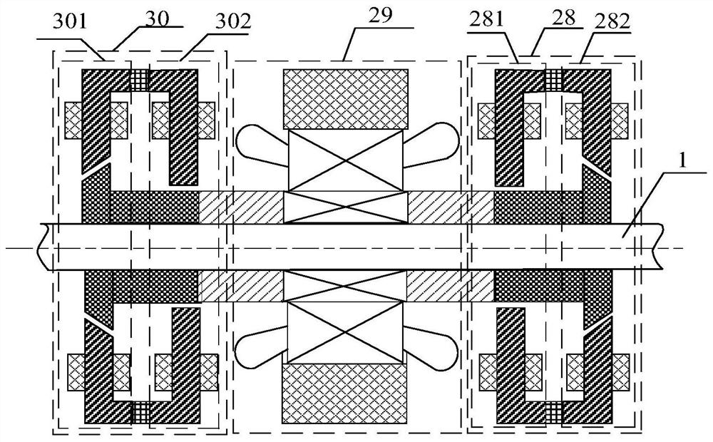
[0021] like figure 1 and figure 2 As shown, the present invention includes a rotating shaft 1 and a high-speed spindle motor 29, the high-speed spindle motor 29 includes a high-speed spindle motor stator 16 and a high-speed spindle motor rotor 17, and the high-speed spindle motor rotor 17 is coaxially sleeved in the axial middle of the rotating shaft 1 position to drive the rotating shaft 1 to rotate. There is a radial-axial magnetic bearing on both axial sides of the high-speed spindle motor 29, which are respectively the first radial-axial magnetic bearing 28 and the second radial-axial magnetic bearing 30, and the first radial-axial magnetic bearing 30. The structure of the axial magnetic bearing 28 and the second radial-axial magnetic bearing 30 is exactly the same, but they are installed axially symmetrically with respect to the center point of the high-speed spindle motor 29 , that is, they are installed backwards.

[0022] A steel cylinder is wrapped concentrically o...


PUM

PropertyMeasurementUnit
diameteraaaaaaaaaa

Abstract

The invention discloses an electric spindle system supported by double radial six-pole hybrid magnetic bearings with different magnetic pole surfaces, which drives a rotating shaft to rotate, and radial-axial magnetic bearings which have the same structure and are symmetrical relative to the central point of a high-speed spindle motor are respectively arranged on the left side and the right side in the axial direction of a high-speed spindle motor; the first radial-axial magnetic bearing on the axial right side is composed of a first radial magnetic bearing, a first annular permanent magnet and a first conical magnetic bearing which are sequentially arranged in the axial direction, the first radial magnetic bearing is close to the high-speed spindle motor, and the first conical magnetic bearing is composed of a first conical stator, a first conical rotor and a first conical magnetic bearing control coil; and the conical outer surface of the first conical rotor and the inner surface ofa first conical stator magnetic pole are conical, and the large end of the conical inner surface of the first conical stator magnetic pole is close to the first radial magnetic bearing. The conical magnetic bearing is adopted to replace an axial magnetic bearing, a thrust disc can be removed, the axial length of the rotor is shortened, and the critical rotating speed of the rotor can be increased.

Description

technical field [0001] The invention belongs to the field of non-contact magnetic suspension bearings, in particular to an electric spindle system supported by a hybrid magnetic suspension bearing, which is suitable for high-speed, ultra-high-speed and high-precision numerical control machine tools. Background technique [0002] The electric spindle supported by traditional contact bearings (sliding bearings, rolling bearings) has a series of problems such as thermal deformation of the spindle, short life, and insufficient shock resistance due to contact friction and wear between the spindle and the bearing. Magnetic suspension bearings (magnetic bearings for short) use energized coils or permanent magnets to generate electromagnetic force to suspend the rotor in the air, so that there is no mechanical contact between the stator and the rotor, and it has no friction, no wear, no pollution, high speed, high precision, high A series of incomparable advantages of traditional be...

Claims


Application Information

Patent Timeline
Patent Type & Authority Applications(China)
IPC IPC(8): F16C32/04B23B19/02
CPCB23Q1/70F16C32/0459F16C32/0465F16C32/0491F16C2322/39
Inventor 吴梦瑶朱熀秋朱利东华逸舟刘钙
Owner JIANGSU UNIV
Why Eureka
Try Eureka