Method and system for monitoring working temperature of spherical transducer

A technology of working temperature and transducer, which is applied to parts of thermometers, thermometers, and thermometers using electric/magnetic elements that are directly sensitive to heat, can solve the problem of not finding the same technology of the present invention, not finding the same method, temperature The sensor is not suitable for temperature monitoring of spherical piezoelectric ceramics, etc., to improve the temperature measurement accuracy, reduce the impact, and realize the effect of temperature warning

Inactive Publication Date: 2021-01-01
上海船舶电子设备研究所
View PDF8 Cites 0 Cited by
  • Summary
  • Abstract
  • Description
  • Claims
  • Application Information

AI Technical Summary

Problems solved by technology

However, the existing temperature sensors are not suitable for monitoring the temperature of the inner and outer walls of spherical piezoelectric ceramics.
[0006] For the method of measuring the working temperature of the spherical transducer, no similar technology to the present invention has been found to exist, and no similar method has been found to exist in documents and documents.

Method used


Image

  • Method and system for monitoring working temperature of spherical transducer
  • Method and system for monitoring working temperature of spherical transducer
  • Method and system for monitoring working temperature of spherical transducer

Examples


Embodiment 1

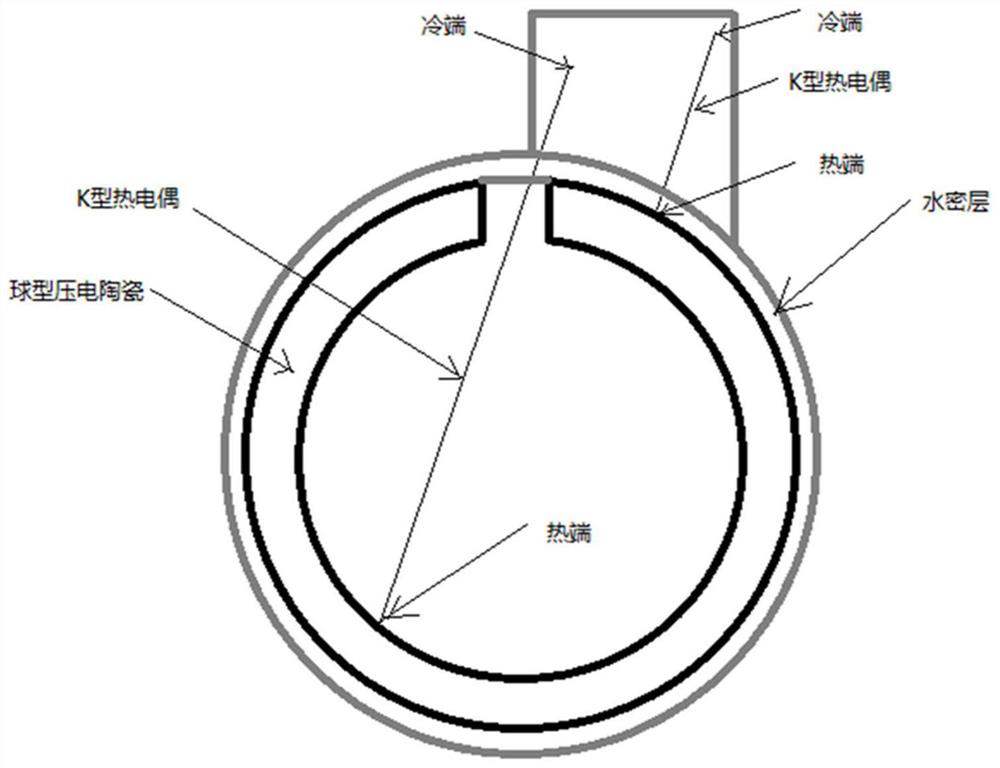
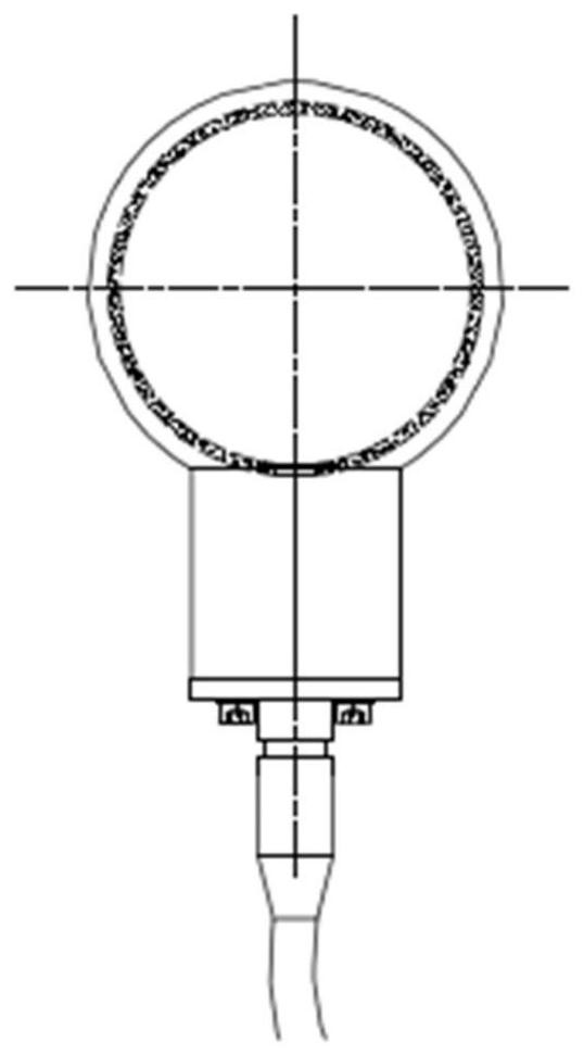
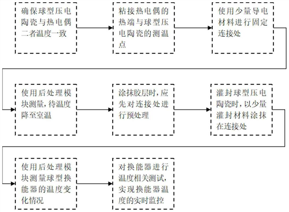
[0044] In this embodiment, a method for monitoring the operating temperature of a spherical transducer provided according to the present invention, such as image 3 As shown, specifically, in step 1, it will be as figure 2 The spherical piezoelectric ceramic and the K-type thermocouple shown in are placed at room temperature at the same time, and the temperature change of the two is accelerated by using a hair dryer or other equipment or left for a long enough time, so that the temperature of the spherical piezoelectric ceramic is the same as that of the K-type thermocouple. The temperature of the pair is the same.

[0045] In step 2, use solder to weld or use an adhesive layer with better thermal conductivity to bond the hot end of the K-type thermocouple and the temperature measuring point of the spherical piezoelectric ceramic to ensure that the hot end potential of the K-type thermocouple can be better It changes with the temperature change of the temperature measuring p...

Embodiment 2

[0053] This embodiment is based on embodiment 1, optimizes and implements in the following five aspects:

[0054] (1) In order to reduce the influence of the measurement response time, this embodiment selects a K-type thermocouple with a small diameter at the measuring end for the test, and selects an adhesive layer with better thermal conductivity to bond the piezoelectric ceramic ball and the thermocouple of the K-type thermocouple. end, so that the thermal response time is shortened, and the measured object and the temperature measuring element are more likely to achieve thermal equilibrium, so that the measurement accuracy of the present invention is increased.

[0055] (2) In order to reduce the influence of the temperature measurement point deviation on the measurement, in this embodiment, the point where the heat generation phenomenon is more obvious in the transducer is selected as the temperature measurement point. The position of the temperature measurement point mus...


PUM


Abstract

The invention provides a method and system for monitoring the working temperature of a spherical transducer. The method comprises the steps: ensuring that the temperature of spherical piezoelectric ceramic and the temperature of a thermocouple are consistent; bonding the hot terminal of the thermocouple with a temperature measuring point of the spherical piezoelectric ceramic; fixing the joint byusing a small amount of conductive material; using a post-processing module for measurement, and reducing the temperature to the room temperature; when the adhesive layer is smeared, preprocessing thejoint firstly; when the spherical piezoelectric ceramic is encapsulated, smearing a small amount of encapsulating material at the joint; using a post-processing module for measuring the temperature change condition of the spherical transducer; and carrying out temperature related test on the transducer to realize real-time monitoring of the temperature of the transducer. According to the invention, the K-type thermocouple is selected as a temperature sensor, and an effective transducer temperature monitoring system is established through a proper scheme in combination with the characteristicsof the spherical transducer, so that the measurement method is simple and convenient and has relatively high engineering applicability.

Description

technical field [0001] The invention relates to the field of transducer working state monitoring, in particular to a method and system for monitoring the working temperature of a spherical transducer. Background technique [0002] In the development of modern underwater acoustics, underwater acoustic equipment shows a trend towards high power, high stability, and long-term use. In underwater acoustic equipment, the importance of the transducer has become increasingly prominent, and it has become the focus of underwater acoustic equipment research. When the transducer is used to emit sound wave signals, due to the energy loss of the transducer itself, all the electrical energy cannot be converted into sound energy, and most of the lost electrical energy is converted into heat energy. At the same time, since the radiating surface of the transducer is often covered by a watertight layer, and the thermal conductivity of the watertight layer is generally poor, the heat energy ca...

Claims


Application Information

Patent Timeline
Patent Type & Authority Applications(China)
IPC IPC(8): G01K7/04G01K1/14
CPCG01K7/04G01K1/14
Inventor 张明宇王艳彭策沈明杰刘佳李凡
Owner 上海船舶电子设备研究所
Why Eureka
Try Eureka