Road network matching method and device, electronic equipment and medium

A road network matching and road network technology, which is applied in the direction of measuring devices, radio wave measurement systems, satellite radio beacon positioning systems, etc., can solve problems such as interference, inaccurate results, and large amount of calculations in the later stage, so as to reduce computing resources. Requirements, simple calculation process, and the effect of meeting calculation needs

Pending Publication Date: 2021-01-01
北京市生态环境监测中心
View PDF6 Cites 3 Cited by
  • Summary
  • Abstract
  • Description
  • Claims
  • Application Information

AI Technical Summary

Problems solved by technology

However, the above methods all have limitations in use. For example, the proximity algorithm based on Euclidean distance requires the number of sampling points between trajectories to be equal, which is difficult to achieve in actual operation; Effective discrimination leads to inaccurate results; the difficulty of the grid method is that it is difficult to define the division of the grid size, so it brings great uncertainty and artificial interference to the final result
[0005] In the above method, it is necessary to employ professional data collection personnel, and use professional vehicles and positioning equipment to measure roads and vehicle trajectories. There are often problems such as long information acquisition cycle, large amount of calculation in the later stage, and high equipment maintenance costs.
However, some methods using GPS / GNSS and other means for motor vehicle road network matching, although they improve the accuracy, lead to a geometric progression in the amount of calculations, so that real-time matching operations cannot be realized. In actual operation, this method greatly limits Practicality and scope of application sacrifice timeliness and efficiency

Method used


Image

  • Road network matching method and device, electronic equipment and medium
  • Road network matching method and device, electronic equipment and medium
  • Road network matching method and device, electronic equipment and medium

Examples


Embodiment Construction

[0029] Hereinafter, embodiments of the present disclosure will be described with reference to the drawings. It should be understood, however, that these descriptions are exemplary only, and are not intended to limit the scope of the present disclosure. In the following detailed description, for purposes of explanation, numerous specific details are set forth in order to provide a thorough understanding of the embodiments of the present disclosure. It may be evident, however, that one or more embodiments may be practiced without these specific details. Also, in the following description, descriptions of well-known structures and techniques are omitted to avoid unnecessarily obscuring the concepts of the present disclosure.

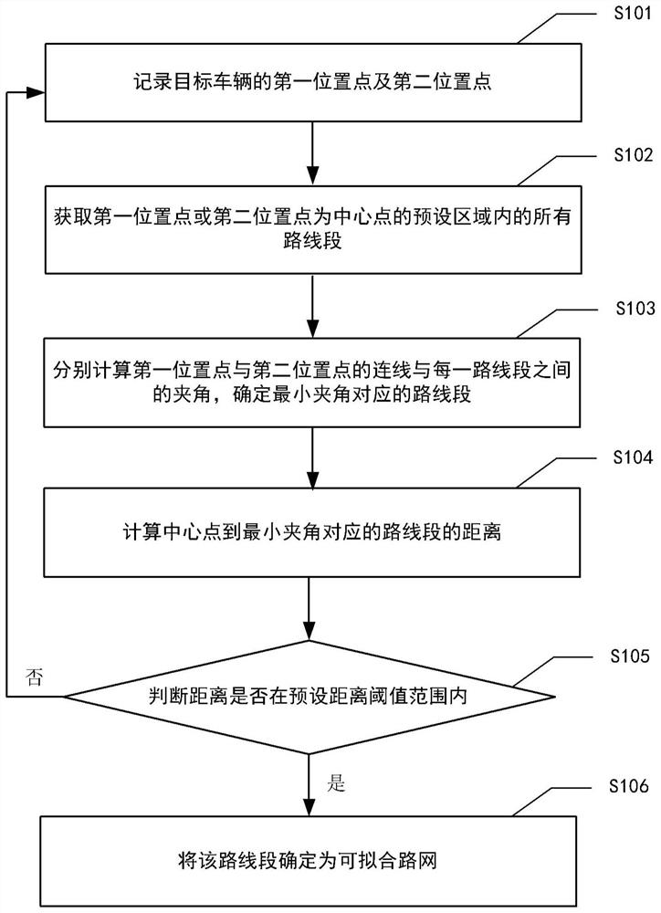
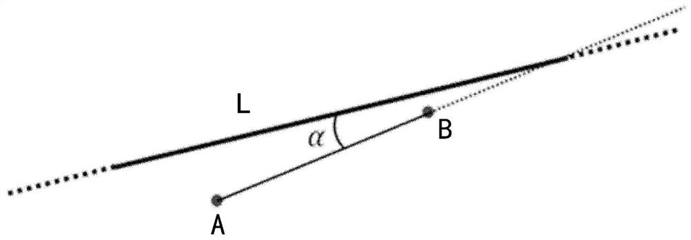
[0030] Embodiments of the present disclosure provide a road network matching method and a road network matching device using the method. The method includes recording a first location point and a second location point of a target vehicle. Acquire all rout...


PUM


Abstract

The invention provides a road network matching method. The road network matching method comprises the steps of recording a first position point and a second position point of a target vehicle; acquiring all route segments in a preset area taking the first position point or the second position point as a central point; respectively calculating an included angle between a connecting line of the first position point and the second position point and each route segment, and determining the route segment corresponding to the minimum included angle; calculating the distance from the central point tothe route segment corresponding to the minimum included angle; and judging whether the distance is within a preset effective distance threshold range or not, and if so, determining the route segmentas a fitting road network route. According to the method, the operation process is simple, the required resources are few, so that higher operation efficiency is achieved, higher calculation precisioncan be maintained all the time to meet the calculation requirement, stream processing calculation can be supported subsequently, and good expansibility is achieved. The invention further provides a road network matching device, electronic equipment and a readable storage medium.

Description

technical field [0001] The present disclosure relates to the field of vehicle driving, and in particular to a road network matching method, device, electronic equipment and media. Background technique [0002] Roads are a very important basic geographical element in maps. With the increasing popularity of 5G and big data technologies, the rapid update of road network data is very important for the implementation of vehicle navigation, emergency response, and even the Internet of Vehicles. meaning and value. [0003] The use of GPS devices to carry out vehicle trajectory research has been more and more widely used. Road network mapping is the basis for research on motor vehicle trajectories and emissions. The main purpose of road network mapping is to match vehicle positioning data collected in GPS with existing road network data through a specific algorithm to accurately display motor vehicle driving. The real track of the real track, so as to play the role of positioning,...

Claims


Application Information

Patent Timeline
Patent Type & Authority Applications(China)
IPC IPC(8): G01S19/42
CPCG01S19/42
Inventor 刘保献杨妍妍沈秀娥李豪文张泽佳鹿海峰卢洋张琳孙彤卉邹本东
Owner 北京市生态环境监测中心
Why Eureka
Try Eureka