
gas discharge lamp

A gas discharge lamp and terminal electrode technology, applied in the field of lighting, can solve problems such as long time required, short circuit of terminal electrodes, and reduced heat conduction efficiency, so as to improve the reliability of use, increase the start-up speed, and reduce the difficulty of start-up.

Active Publication Date: 2021-05-28
南京炯华照明科技有限公司
View PDF0 Cites 1 Cited by
  • Summary
  • Abstract
  • Description
  • Claims
  • Application Information

AI Technical Summary

Problems solved by technology

[0004] However, due to the limitation of the structural space of the gas discharge lamp, the auxiliary starting module is usually placed in the dark corner of the arc tube light source radiation and heat radiation, and the light and heat radiation emitted by the arc tube cannot directly reach the auxiliary starting module and its metal sheets. After assisting to start the arc tube, the heat required to disconnect the electrical connection between the terminal electrode and the wire is completely conducted by the molecular motion of the gas filled inside the gas discharge lamp. In this way, the metal sheet is disconnected slowly and inefficiently. Poor reliability and high requirements for the purity of the filling gas in the gas discharge lamp
In addition, after the gas discharge lamp is used for a long time, the heat conduction efficiency in the lamp decreases, the heat conducted by the filling gas decays rapidly, and the reliability of the metal sheet disconnection is further reduced
Therefore, in the prior art, after the metal sheet of the auxiliary starting module assists in starting the arc tube, it takes a long time for the metal sheet to disconnect the electrical connection between the terminal electrode and the wire on the wall of the arc tube, so that the terminal electrode continues to short circuit, resulting in Attenuation of the electrode tip of the terminal electrode, blackening of the inside of the arc tube, etc.

Method used


Image

  • gas discharge lamp
  • gas discharge lamp
  • gas discharge lamp

Examples


Embodiment Construction

[0036] In order to make the purpose, technical solution and advantages of the present application clearer, the present application will be further described in detail below in conjunction with the accompanying drawings and embodiments. It should be understood that the specific embodiments described here are only used to explain the present application, and are not intended to limit the present application.

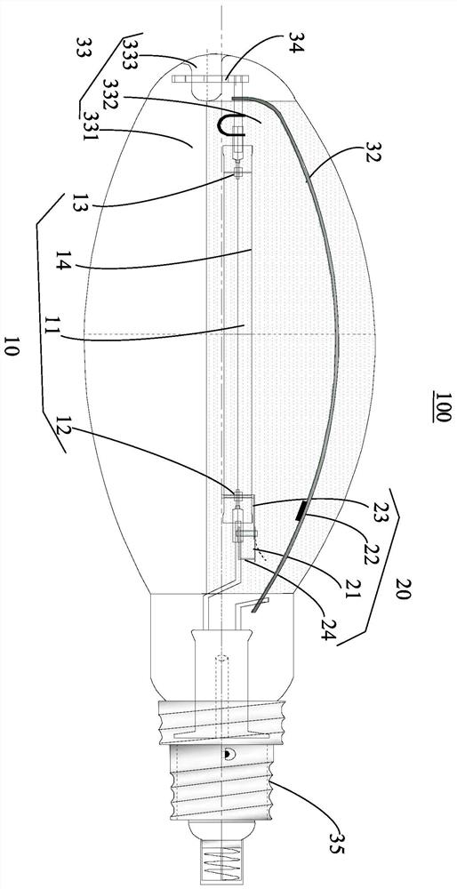
[0037] see figure 1, an embodiment of the present application provides a gas discharge lamp 100 . The gas discharge lamp 100 is a high pressure gas discharge lamp, for example, a high pressure sodium lamp, a high pressure mercury lamp, or a metal halide lamp such as a quartz metal halide lamp or a ceramic metal halide lamp.

[0038] In this embodiment, the gas discharge lamp 100 includes an arc tube 10 and an auxiliary starting module 20 .

[0039] The arc tube 10 includes an insulating light-transmitting tube body 11 , a first terminal electrode 12 , a second terminal e...


PUM

PropertyMeasurementUnit
reflectanceaaaaaaaaaa

Abstract

The present application provides a gas discharge lamp, comprising: an arc tube, including a tube body, first and second terminal electrodes located at both ends of the tube body, and a wire arranged on the outer wall of the tube and located between the first and second terminal electrodes; The auxiliary starting module is arranged on the side of the first terminal electrode, including a conductive sheet and a photosensitive heat radiator. The conductive sheet is connected to the first terminal electrode and the wire. The conductive sheet is made of a heat-sensitive material, and the photosensitive thermal radiator is arranged adjacent to the conductive sheet. The light radiation and / or thermal radiation output by the arc tube is used to irradiate the conductive sheet, and the conductive sheet is deformed by heat to disconnect the electrical connection between the wire and the first terminal electrode. This application shortens the discharge distance through the conductive sheet, increases the start-up speed of the arc tube and reduces the difficulty of starting, and irradiates the light radiation and / or thermal radiation output by the arc tube to the conductive sheet through the light-induced heat radiator, which can prevent the conductive sheet from being connected to the wire for a long time And the early attenuation of the electrode tip of the first end electrode caused by the first end electrode, the blackening of the inside of the arc tube and other problems.

Description

technical field [0001] The present application relates to the technical field of lighting, in particular, to a gas discharge lamp. Background technique [0002] In modern life, gas discharge lamps are used more and more widely. The arc tube is a key component of a high intensity discharge lamp. When the gas discharge lamp is started, an arc is generated between the electrodes at both ends of the arc tube. Due to the high temperature of the arc, the luminescent material in the tube is heated and evaporated to form steam. The electrons emitted by the cathode hit the atoms of the discharge material during the movement to the anode, causing It obtains energy to generate ionization excitation, and then returns from the excited state to the stable state; or changes from the ionized state to the excited state, and then returns to the stable state for an infinite cycle, and the excess energy is released in the form of light radiation, which produces light. In the prior art, the st...

Claims


Application Information

Patent Timeline
Patent Type & Authority Patents(China)
IPC IPC(8): H01J61/02H01J61/10H01J61/36H01J61/54
CPCH01J61/02H01J61/10H01J61/36H01J61/548
Inventor 张长征
Owner 南京炯华照明科技有限公司
Learn More