Method for performing fundus refractive compensation judgment and imaging optimization by using OCT signal

An imaging and signal technology, applied in ophthalmoscopes, eye testing equipment, applications, etc., can solve problems affecting measurement and increasing hardware costs, achieve fast and accurate refractive compensation, reduce costs, and overcome large inclinations in positions Effect

Active Publication Date: 2021-01-05
SUZHOU UNIV
View PDF14 Cites 1 Cited by
  • Summary
  • Abstract
  • Description
  • Claims
  • Application Information

AI Technical Summary

Problems solved by technology

However, this method requires the subject to observe the target and give feedback, and the subject needs to be trained first, and the head movement may affect the subsequent OCT measurement during the feedback process
The patent for invention CN102824159B "Fundus OCT Automatic Jumping System, Equipment and Method" discloses an automatic adjustment device that uses a microlens array and detects the distance between two adjacent points of the beam focus point detected by a detector, but This method requires additional detectors and increases hardware costs

Method used


Image

  • Method for performing fundus refractive compensation judgment and imaging optimization by using OCT signal
  • Method for performing fundus refractive compensation judgment and imaging optimization by using OCT signal
  • Method for performing fundus refractive compensation judgment and imaging optimization by using OCT signal

Examples


Embodiment

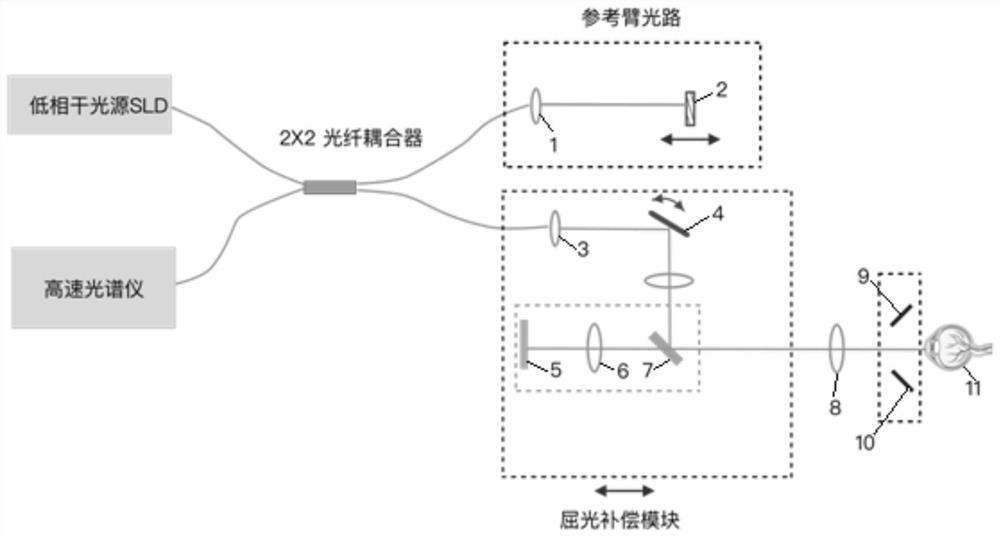
[0043] Embodiment: the system device figure of the present invention is as figure 1 As shown, the system device includes: a low-coherence light source SLD, a high-speed spectrometer, a reference arm optical path, a yield compensation module, an eyepiece 8, and a pupil positioning module; the reference arm optical path includes a first fiber collimator 1 and a mirror 2, and the yield compensation module includes Second fiber collimator 3, two-dimensional scanning galvanometer 4, internal fixation target 5, lens 6, dichroic mirror 7, internal fixation target 5, lens 6, dichroic mirror 7, eyepiece 8, pupil positioning The centers of the modules are located on the same optical axis line. The pupil positioning module includes a right camera 9 and a left camera 10, and the right camera 9 and the left camera 10 are symmetrically arranged on both sides of the eyepiece 8 for the pupil positioning of the human eye 11. When the optical axis of the eyepiece 8 is in line with the human eye...


PUM


Abstract

The embodiment of the invention discloses a method for performing fundus refractive compensation judgment and imaging optimization by using an OCT signal. The method comprises the following steps of:S1, controlling a reference arm optical path: finding a retina structure in an image and adjusting the retina structure to a proper position in the image by calculating the concavity and convexity ofthe retina structure and an imaging position; S2, performing automatic refractive compensation: controlling the optical path difference between the reference arm optical path and a sample arm scanningbeam optical path to be a fixed value, and finding an image with the strongest signal through a hill climbing method for refractive compensation; S3, performing left-right fine adjustment on the retina structure: judging the left-right deviation of the retina structure, and controlling a Y-axis motor to perform horizontal adjustment according to the deviation; and S4, adjusting the retina imagingposition: adjusting the reference arm optical path again according to the image intensity so as to adjust the height position of the retina in the image. According to the method for performing fundusrefractive compensation judgment and imaging optimization by using the OCT signal, the cost can be reduced, rapid and accurate refractive compensation can be realized, and meanwhile, retina imaging is optimized.

Description

technical field [0001] This application relates to the technical field of retinal image imaging, in particular to a method for using OCT signals to determine fundus refraction compensation and optimize imaging. Background technique [0002] The fundus retina is a microscopic structure of the human body. Many eye diseases and some systemic diseases can be reflected on the fundus retina. Optical coherence tomography (OCT) is a fundus retinal imaging system that can acquire three-dimensional fundus images. OCT equipment uses low-coherent light interference imaging technology, and the optical path difference between the scanning probe beam and the reference beam needs to be within a certain range to be clearly imaged. In order to use OCT equipment to obtain clear fundus images, the usual OCT equipment needs to perform two steps of diopter compensation and imaging height adjustment of the scanning optical path. Refractive compensation refers to adjusting the optical path for hu...

Claims


Application Information

Patent Timeline
Patent Type & Authority Applications(China)
IPC IPC(8): A61B3/10A61B3/12A61B3/14G06F17/14G06T7/00
CPCA61B3/102A61B3/12A61B3/14G06T7/0012G06F17/142G06T2207/30041
Inventor 陈新建王波刘铭
Owner SUZHOU UNIV
Why Eureka
Try Eureka