Clamping and welding mechanism for pipe pile plate skirt roll welding equipment

A welding mechanism and coil welding technology, which is applied in the field of machinery, can solve the problems of large space occupation, heavy labor intensity, and high noise, and achieve the effect of saving space and stabilizing the welding process

Pending Publication Date: 2021-01-05
福州嘉胜自动化科技有限公司
View PDF0 Cites 0 Cited by
  • Summary
  • Abstract
  • Description
  • Claims
  • Application Information

AI Technical Summary

Problems solved by technology

At present, most of the welding work is done manually by workers. The labor intensity is high, the working environment is poor, and the labor cost is high. At the same time, due to manual errors and other reasons, quality problems are prone to occur.
[0003] However, the existing pipe pile plate skirt welding equipment has high cost, complicated control, and takes up a large space. During the process of moving the plate skirt, it is noisy and wears heavily. While the life of the equipment is affected to a certain extent, it will also affect the work efficiency and It is not a good choice for some enterprises and manufacturers

Method used


Image

  • Clamping and welding mechanism for pipe pile plate skirt roll welding equipment
  • Clamping and welding mechanism for pipe pile plate skirt roll welding equipment
  • Clamping and welding mechanism for pipe pile plate skirt roll welding equipment

Examples


Embodiment Construction

[0019] The present invention will be described in further detail below in conjunction with the accompanying drawings.

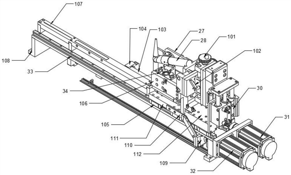
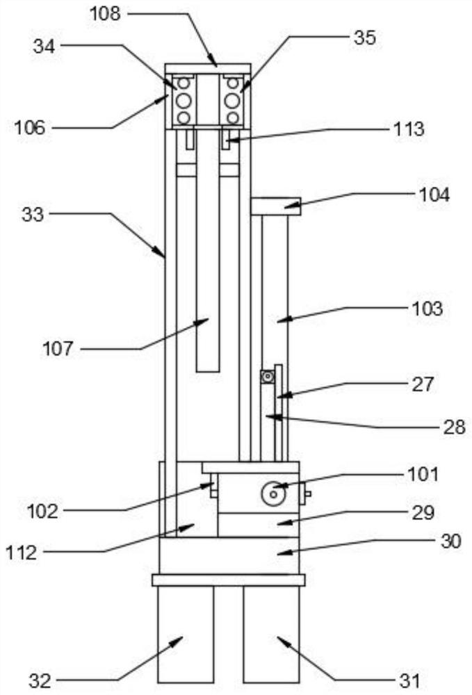
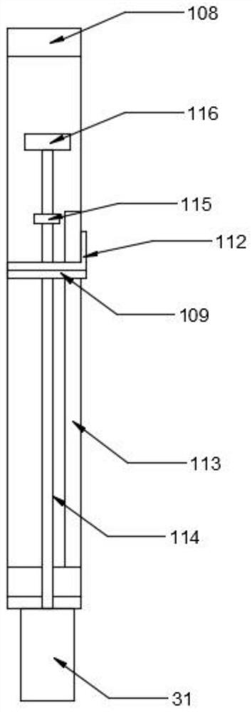
[0020] combined with figure 1 To attach image 3 , a clamping welding mechanism for pipe pile plate skirt roll welding equipment, including a few-shaped support plate 108, one side of the several-shaped support plate 108 is threadedly connected with a plate skirt clamping mechanism servo motor 32 and a welding torch Mechanism servo motor 31, the top of described several-shaped support plate 108 is connected with slide rail one 33, is provided with fixed plate 112 above one end of described slide rail one 33, and is provided with slide rail above slide rail one 33. block 105, the upper end of the slider 105 is fixedly connected with a slide plate 111, the upper side of the slide plate 111 is provided with a plate skirt positioning roller clamping cylinder 34, and the other side above the slide plate 111 is provided with a plate skirt fixed clamping Cylinder ...


PUM


Abstract

The invention discloses a clamping and welding mechanism for pipe pile plate skirt roll welding equipment. The clamping and welding mechanism comprises a n-shaped support plate. One side of the n-shaped support plate is in threaded connection with a plate skirt clamping mechanism servo motor and a welding gun propelling mechanism servo motor. A first sliding rail is arranged on the n-shaped support plate. A fixing plate is arranged above the first sliding rail. A sliding block is arranged on the first sliding rail in a sliding manner. A sliding plate is arranged on the sliding block. A plate skirt positioning roller clamping air cylinder is arranged on one side of the upper face of the sliding plate. A plate skirt fixing and clamping air cylinder is arranged on the other side of the sliding plate. The side face of the sliding plate is connected with a connecting plate. The lower end of the connecting plate is connected with a positioning plate. A welding gun positioning and adjusting mechanism is arranged above the fixing plate. A welding gun is arranged at the front end of the welding gun positioning and adjusting mechanism. The rear end of the welding gun positioning and adjusting mechanism is connected with a welding gun lifting air cylinder. The output end of the welding gun propelling mechanism servo motor is connected with a first guide rod. A support is arranged at the other end of the first guide rod. Compared with the prior art, the clamping and welding mechanism is high in safety and stability, low in failure rate, simple in structure and smooth in roll welding process.

Description

technical field [0001] The invention relates to the field of mechanical technology, in particular to a clamping welding mechanism for pipe pile plate skirt rolling welding equipment. Background technique [0002] With the continuous development of the manufacturing industry, the demand for pipe pile plate skirt welding is also increasing. At present, most of the welding work is done manually by workers. The labor intensity is high, the working environment is poor, and the labor cost is high. At the same time, due to manual errors and other reasons, quality problems are prone to occur. [0003] However, the existing pipe pile plate skirt welding equipment has high cost, complicated control, and takes up a large space. During the process of moving the plate skirt, it is noisy and wears heavily. While the life of the equipment is affected to a certain extent, it will also affect the work efficiency and The income is not a good choice for some enterprises and manufacturers. ...

Claims


Application Information

Patent Timeline
IPC IPC(8): B23K37/02B23K37/00B23K37/04
CPCB23K37/006B23K37/02B23K37/0443
Inventor 吴杰民游剑峰黄鼎林钻
Owner 福州嘉胜自动化科技有限公司
Why Eureka
Try Eureka