Reciprocating rolling material forming device

A reciprocating, material technology, applied in the direction of material forming presses, presses, manufacturing tools, etc., can solve the problems of poor feeding, accumulation, difficult to make bar shape and size adjustment, etc., to increase the evaporation surface area, increase Large evaporation area, good effect of making strips

Pending Publication Date: 2021-01-05
AMCON FUJIAN ENVIRONMENT PROTECTION EQUIP CO LTD
View PDF1 Cites 5 Cited by
  • Summary
  • Abstract
  • Description
  • Claims
  • Application Information

AI Technical Summary

Problems solved by technology

The disadvantages of this structure are: 1. The extrusion force of the material comes from the gravity of the material itself and the extrusion force of the double rollers when they are rotating, which cannot ensure a stable downward extrusion force
2. Some extruded materials are continuous and easy to cause accumulation
3. It is impossible to make grooves with smaller pores, because the grooves are too small to be squeezed normally, and the materials retained in the grooves cannot be cleaned in time
4. It is impossible to adjust the size of the groove more flexibly, which makes it difficult to flexibly adjust the shape and size of the strip according to the shape of the material
5. It is necessary to set up a bridge breaking device, otherwise the material is easy to agglomerate or bridge in the feeding bin, resulting in poor feeding

Method used


Image

  • Reciprocating rolling material forming device
  • Reciprocating rolling material forming device
  • Reciprocating rolling material forming device

Examples


no. 1 example

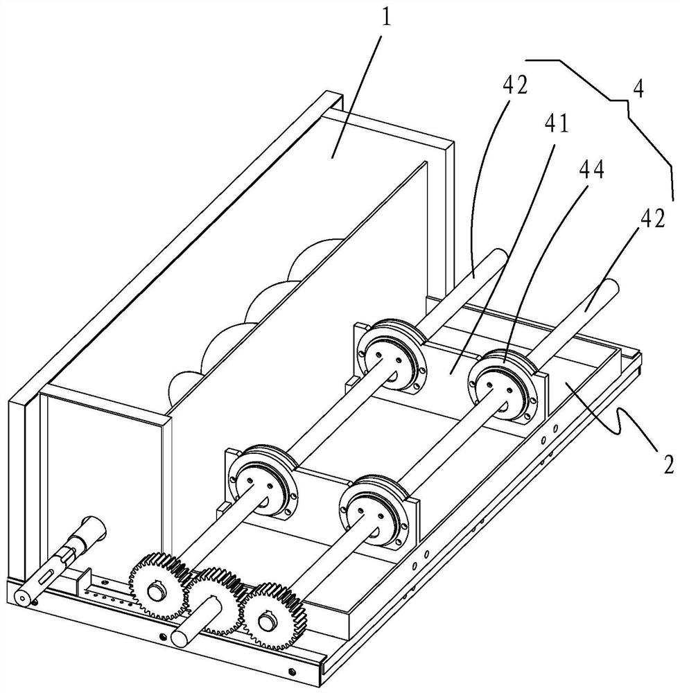
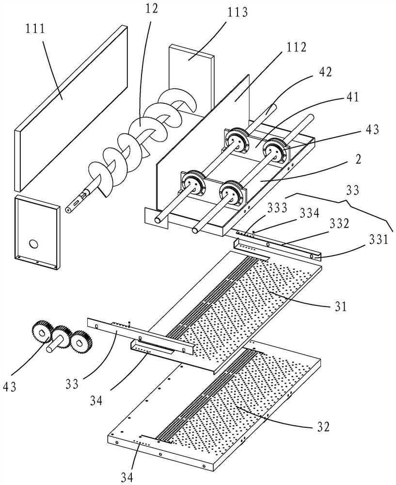
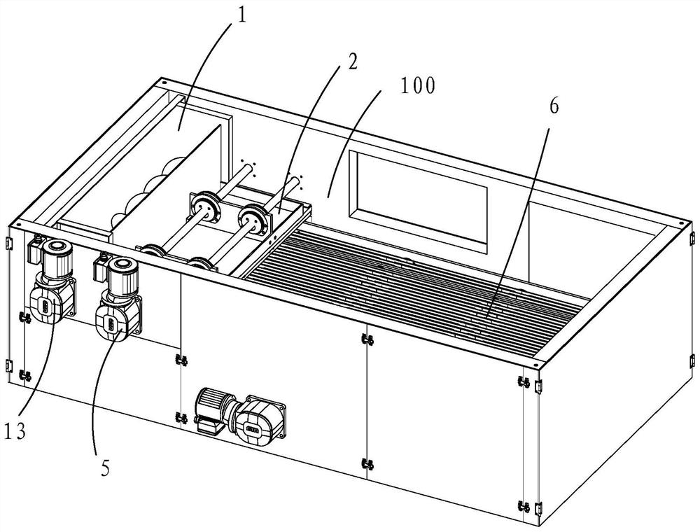
[0032] like figure 1 and figure 2 As shown, a reciprocating rolling material forming device includes: a feeding mechanism 1, a rolling plate 2, and two stacked and fixedly connected pressure bearing plates 31, 32.

[0033] The two pressure bearing plates 31 and 32 are provided with a plurality of circular or elongated holes; the upper pressure bearing plate 31 is a movable pressure bearing plate, and the lower pressure bearing plate 32 is an immovable pressure bearing plate; The pressure bearing plate 32 located below is fixed on the frame 100 on both sides (in practice, the frame 100 can be the two side walls of the drying equipment), and its two sides are respectively fixedly connected with an L-shaped firmware guide rail 33, L-shaped One side 331 of the firmware guide rail part 33 and the side of the pressure bearing plate 32 are fixed on the frame 100 on both sides, and the other side 332 is parallel to the pressure bearing plate 32, and the gap between the two forms a g...

no. 2 example

[0042] see Figure 3 to Figure 7 As shown, in the second embodiment, a quick-transfer drying platform 6 is set under the pressure-bearing plate 32 in the first embodiment, so that the formed material is transferred quickly. For the specific structure of the fast-transfer drying platform 6 , please refer to the stacked push-type material delivery platform in a peristaltic push-type drying equipment disclosed in Chinese invention patent 2019107487193.6.

[0043] Working process: The material enters from the upper part of the feeding bin 11 of the feeding mechanism 1, and through the rotation of the two-way screw shaft 12, the material is evenly transported to the entire feeding bin 11, and the material can be fed into the rolling plate 2 and In the gap formed by the pressure bearing plates 31, 32. Since the baffle plate 112 connected to the rolling plate 2 performs reciprocating synchronous circular motion, material accumulation or bridging can be avoided. At the same time, the...


PUM


Abstract

A reciprocating rolling material forming device comprises a feeding mechanism, a rolling plate and a bearing plate, wherein the rolling plate and the bearing plate are arranged in parallel, the bearing plate is located below the rolling plate, and a plurality of holes are formed in the bearing plate; the feeding mechanism is located at the same ends of the rolling plate and the bearing plate, andmaterials enter the gap between the rolling plate and the bearing plate from the feeding mechanism; at least one of the rolling plate and the bearing plate is connected with a driving mechanism, and the driving mechanism is connected with a first power source; and the first power source drives the driving mechanism to drive at least one of the rolling plate and the bearing plate to do reciprocating synchronous circular motion, so that the materials on the bearing plate are rolled and poked, and the materials are extruded and formed from the holes of the bearing plate located below. According to the device, the materials are periodically and intermittently rolled, so that the formed materials are short, accumulation is avoided, and the evaporation area can be enlarged.

Description

【Technical field】 [0001] The invention belongs to the technical field of material separation and forming, and specifically refers to a reciprocating rolling material forming device. 【Background technique】 [0002] The dehydration of the material through the filter will produce a large amount of solid filter cakes, but these filter cakes still contain high moisture. Therefore, the filter cakes need to be evaporated to remove the contained water through the high temperature in the dryer chamber, so that After the filter cake is dried, it can be stored or transported for reuse. When the filter cake enters the dryer chamber for drying, it enters the chamber through the feeding device installed at the top feed inlet at the upper end of the dryer, so that the filter cake enters the dryer chamber to remove moisture to achieve the purpose of drying. [0003] When the filter cake enters the dryer for drying, it is found that there are defects in the drying of the filter cake enterin...

Claims


Application Information

Patent Timeline
Patent Type & Authority Applications(China)
IPC IPC(8): B30B11/22B30B15/30B30B15/32
CPCB30B11/228B30B15/302B30B15/32
Inventor 郑朝志
Owner AMCON FUJIAN ENVIRONMENT PROTECTION EQUIP CO LTD
Why Eureka
Try Eureka