
Constant-voltage constant-current loop control system and control method thereof

A loop control, constant voltage and constant current technology, applied in control/regulation systems, circuit devices, battery circuit devices, etc., can solve problems such as exceeding preset values, damaging power devices, and overshooting of control quantities

Inactive Publication Date: 2021-01-05
深圳市格睿德电气有限公司
View PDF10 Cites 2 Cited by
  • Summary
  • Abstract
  • Description
  • Claims
  • Application Information

AI Technical Summary

Problems solved by technology

[0002] In the field of digital power supply, in the application scenario of charging the battery, when charging in multiple modes such as constant voltage, constant current, and constant power, in the process of mode switching, some control variables will overshoot and run out of control, such as DC-DC conversion. The inverter is running in constant voltage mode to charge the battery. When the load connected to the battery terminal changes, the battery voltage is pulled down. At this time, the control loop of the constant voltage mode fails, and it is necessary to switch to the constant current mode for charging immediately. In the field of digital power supply , in general, the PID regulation method is used to modulate the loop. Due to the existence of the integral link of the PID regulator, the regulation will have a large inertia, which causes the constant voltage mode control to fail. At the same time, the constant current The mode de-integration has not been completely controlled. In this short-term working condition, the output current will exceed the preset value. In the worst case, it will have a great impact on the stress of the power device, and even Damage to power devices; especially in current high-end charging applications such as new energy vehicles and electric bicycles, under any working conditions, the overshoot of the battery charging current must be controlled within 1%, which poses a very serious problem demanding

Method used


Image

  • Constant-voltage constant-current loop control system and control method thereof
  • Constant-voltage constant-current loop control system and control method thereof

Examples


Embodiment 1

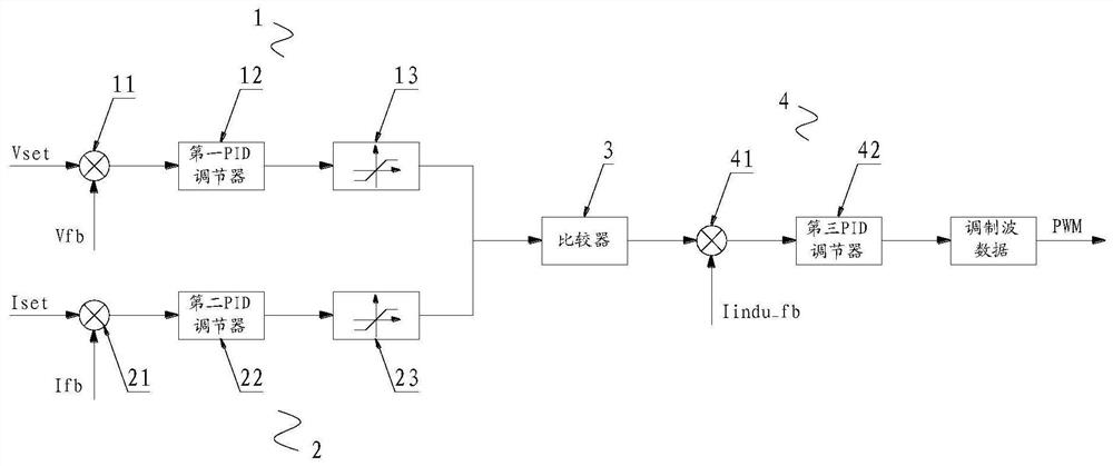
[0048] Please refer to figure 1 , Embodiment 1 of the present invention is:

[0049] A constant voltage constant current loop control system, comprising an outer loop, a comparator 3 and an inner loop, the outer loop includes a voltage loop 1 and a current loop 2, and the inner loop includes an inductor current loop 4, so The input end of the comparator 3 is electrically connected to the output end of the voltage loop 1 and the output end of the current loop 2 respectively, and the output end of the comparator 3 is electrically connected to the input end of the inductance current loop 4, and the inductance current loop 4 The output end of the peripheral device is electrically connected to the actuator of the peripheral device, and the actuator of the peripheral device is an ineffective loop.

[0050]The voltage loop 1 includes a first voltage loop controller, a second voltage loop controller, a first adder 11, a first PID regulator 12 and a first integrator 13, and the curren...

Embodiment 2

[0052] Please refer to figure 1 and figure 2 , the second embodiment of the present invention is:

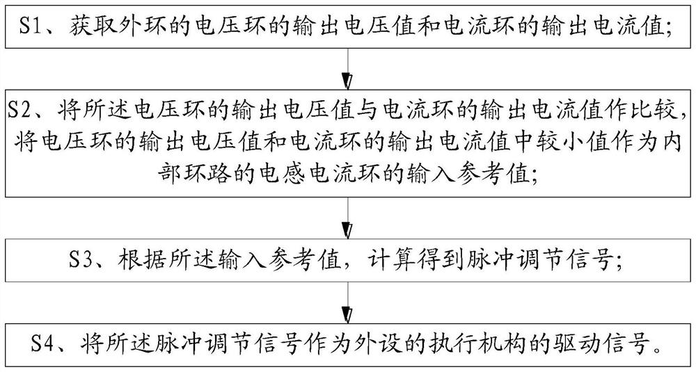
[0053] Please refer to figure 2 , a control method for a constant voltage and constant current loop control system, comprising the following steps:

[0054] S1. Obtain the output voltage value of voltage loop 1 and the output current value of current loop 2 of the outer loop;

[0055] S2. Compare the output voltage value of the voltage loop 1 with the output current value of the current loop 2, and use the smaller value of the output voltage value of the voltage loop 1 and the output current value of the current loop 2 as the inductor current of the inner loop Input reference value for loop 4;

[0056] S3. Calculate and obtain a pulse adjustment signal according to the input reference value;

[0057] S4. Using the pulse adjustment signal as a driving signal of the actuator of the peripheral device.

[0058] The method for obtaining the output voltage value of the voltage...


PUM


Abstract

The invention relates to the technical field of loop switching, in particular to a constant-voltage constant-current loop control system and a control method thereof, the constant-voltage constant-current loop control system comprises an external loop, a comparator and an internal loop, the external loop comprises a voltage loop and a current loop, and the internal loop comprises an inductance current loop; the input end of the comparator is electrically connected with the output end of the voltage loop and the output end of the current loop, the output end of the comparator is electrically connected with the input end of the inductive current loop, and the output end of the inductive current loop is electrically connected with an external actuating mechanism. By arranging the voltage loop, the current loop and the comparator, the comparator judges the output voltage value of the voltage loop and the output current value of the current loop, so that the smaller value of the output voltage value of the voltage loop and the output current value of the current loop of the outer loop can be extracted and input into the inductance current loop to serve as the integral upper and lower limit amplitude limiting value of the non-effective loop. In this way, the out-of-control phenomenon that when the loops are switched, the uneffective loops enter the effective stage can be effectivelyavoided.

Description

technical field [0001] The invention relates to the technical field of loop switching, in particular to a constant voltage and constant current loop control system and a control method thereof. Background technique [0002] In the field of digital power supply, in the application scenario of charging batteries, when charging in multiple modes such as constant voltage, constant current, and constant power, in the process of mode switching, some control variables will overshoot and run out of control, such as DC-DC conversion. The inverter is running in constant voltage mode to charge the battery. When the load connected to the battery changes, the battery voltage is pulled down. At this time, the control loop of the constant voltage mode fails, and it is necessary to switch to the constant current mode for charging immediately. In the field of digital power supply , in general, the PID regulation method is used to modulate the loop. Due to the existence of the integral link o...

Claims


Application Information

Patent Timeline
IPC IPC(8): G05F1/46H02J7/00H02M3/00
CPCG05F1/46H02J7/007H02M3/00
Inventor 刘三山黄宇丽李力学
Owner 深圳市格睿德电气有限公司
Learn More