
Engine bearing frame dynamic strength evaluation method

A technology of engine and dynamic strength, applied in the direction of instrumentation, geometric CAD, design optimization/simulation, etc., can solve the problems of lack of quantitative evaluation methods for exciting force and vibration stress

Active Publication Date: 2021-01-05
AECC SICHUAN GAS TURBINE RES INST
View PDF9 Cites 4 Cited by
  • Summary
  • Abstract
  • Description
  • Claims
  • Application Information

AI Technical Summary

Problems solved by technology

[0004] The invention provides a method for evaluating the dynamic strength of the engine load-bearing frame, which can solve the problem of lack of effective quantitative evaluation methods for exciting force and vibration stress in the design of the dynamic strength of the aero-engine load-bearing frame

Method used


Image

  • Engine bearing frame dynamic strength evaluation method
  • Engine bearing frame dynamic strength evaluation method
  • Engine bearing frame dynamic strength evaluation method

Examples


Embodiment 1

[0029] In order to achieve said object, the present invention has taken following technical scheme:

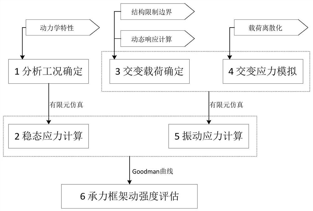
[0030] A method for evaluating the dynamic strength of an engine bearing frame considering alternating loads, including the following steps, please refer to figure 2 :

[0031] Step 1: Analyzing working conditions to determine. According to the dynamic characteristics of the engine, the engine working conditions corresponding to the dynamic strength risk points existing in the load-bearing frame are determined, which is the basis for the strength analysis load.

[0032] Step 2 Steady-state stress calculation. According to the dynamic strength analysis condition obtained in step 1, the engine temperature, pressure and other loads under this condition are used as boundary conditions, and the finite element calculation of the static strength of the load-bearing frame is performed to obtain the steady-state stress of the load-bearing frame under this condition.

[0033] Step 3...

Embodiment 2

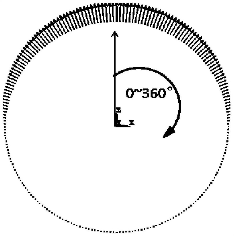
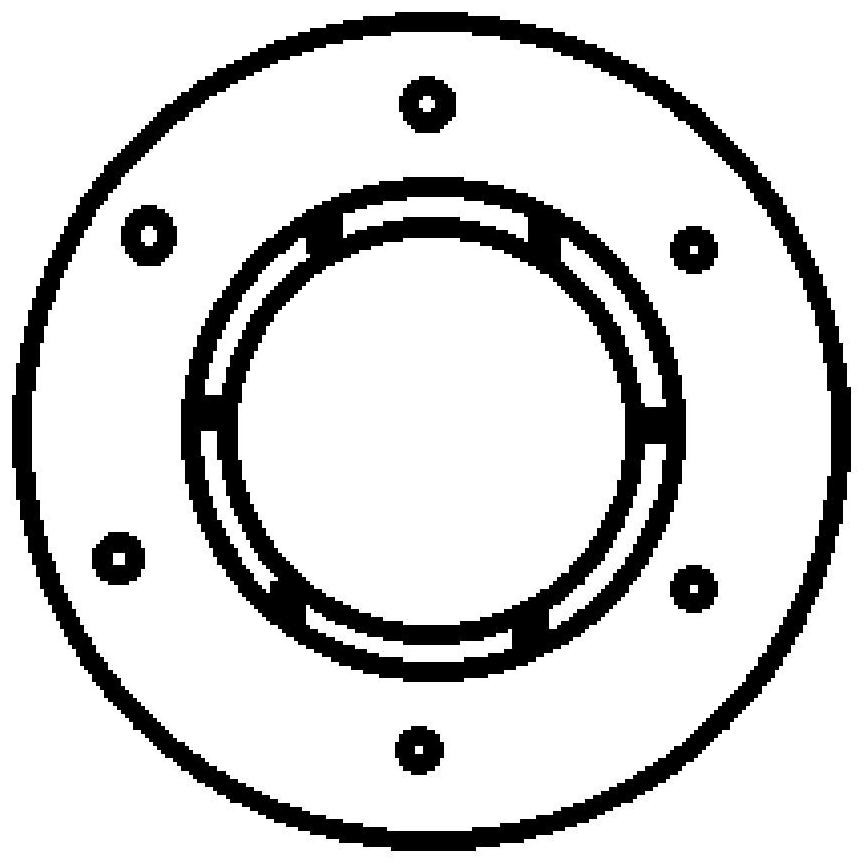
[0038] A method for evaluating the dynamic strength of a load-bearing frame of an engine considering the effect of alternating loads, including steps such as determination of analysis conditions, calculation of steady-state stress, determination of alternating loads, simulation of alternating stress, calculation of vibration stress, and evaluation of dynamic strength. The present invention will be described in further detail below by specific embodiment (with image 3 housing shown as an example):

[0039] The function of the determination of the analysis working conditions is to determine the engine working conditions corresponding to the dynamic strength risk points of the load-bearing frame according to the dynamic characteristics of the engine structure. According to the analysis of rotor dynamics, the load-bearing system produces a large vibration response at a speed of 20000r / min, and the state of the engine corresponding to this speed is taken as an analysis condition f...


PUM


Abstract

The invention provides an engine bearing frame dynamic strength evaluation method, which comprises the steps of taking a preset structure limiting boundary as a limit condition, performing engine dynamic response calculation, and obtaining a limit load borne by a bearing frame when an engine reaches the structure limiting boundary; taking the limit load as an alternating load boundary condition for dynamic stress analysis of the bearing frame; under the alternating load boundary condition, realizing alternating stress simulation of the alternating load by adopting a periodic alternating load discretization method; taking the alternating load as a boundary condition of alternating stress calculation, and performing alternating stress finite element calculation by using the alternating stress simulation method; analyzing the alternating stress change condition of each part in a period to obtain the maximum vibration stress of the force bearing frame; and evaluating the dynamic strength of the force bearing frame according to the calculated steady-state stress of the force bearing frame and the maximum vibration stress value.

Description

technical field [0001] The present application relates to the field of aero-engines, in particular to a method for evaluating the dynamic strength of an engine load-bearing frame. Background technique [0002] The load-bearing frame is the main load-bearing component of an aero-engine. It needs to bear the loads of aerodynamic force, temperature, inertial force, and external vibration of the rotor at the same time. It has the characteristics of complex structural force and important functions. Its static strength evaluation method is mature, and sufficient research and test verification have been carried out at home and abroad; in terms of dynamic strength evaluation, it is found that it is still mainly limited to the design of resonance characteristics, and there is a lack of effective evaluation methods. Once structural fatigue failure occurs due to insufficient dynamic strength design reserves, it will have a serious impact on the engine. [0003] At present, there are c...

Claims


Application Information

Patent Timeline
IPC IPC(8): G06F30/23G06F30/17G06F30/15G06F119/14G06F111/10
CPCG06F30/23G06F30/17G06F30/15G06F2119/14G06F2111/10Y02T90/00
Inventor 江齐朱剑寒姬贺炯卢玲玲孙庆伟刘天文黎方娟高雄兵
Owner AECC SICHUAN GAS TURBINE RES INST
Learn More