Double-frequency filter and mobile terminal

A filter and long-terminal technology, applied to waveguide devices, electrical components, circuits, etc., can solve the problems of complex structure, large size, and insufficient isolation between high and low passbands, and achieve small size, high return loss, and isolation good performance performance

Inactive Publication Date: 2021-01-05
NUBIA TECHNOLOGY CO LTD
View PDF6 Cites 2 Cited by
  • Summary
  • Abstract
  • Description
  • Claims
  • Application Information

AI Technical Summary

Problems solved by technology

[0003] However, the traditional dual-band filter design scheme has technical defects such as complex structure, large volume, and insufficient isolation between high and low passbands.

Method used


Image

  • Double-frequency filter and mobile terminal
  • Double-frequency filter and mobile terminal
  • Double-frequency filter and mobile terminal

Examples


Embodiment 1

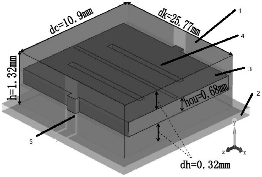
[0054] image 3 It is a three-dimensional perspective view of the first embodiment of the dual-band filter of the present invention. This embodiment proposes a dual-frequency filter, which includes: a metal cavity formed by a metal cavity surface 1 printed on five outer walls and a coplanar waveguide 2, wherein, in figure 1 In the shown xyz-axis three-dimensional space, the cavity surface 1 of five surfaces and the coplanar waveguide 2 form a metal cavity, the coplanar waveguide 2 is perpendicular to the y-axis, and a piece of metal cavity parallel to the coplanar waveguide 2 is arranged in the metal cavity. The metal plate 3, the metal plate 3 is also perpendicular to the y-axis, and three groove lines 4 parallel to the two long end faces of the metal plate 3 are provided on the metal plate 3, wherein the two long end faces of the metal plate 3 are parallel to The two opposite faces of the xy plane are respectively connected to the central conductor strip of the coplanar wav...

Embodiment 2

[0058] Figure 4 It is a top view of the second embodiment of the dual-band filter of the present invention. Based on the above-mentioned embodiment, in this embodiment, a rectangular parallelepiped notch 6 is provided at each of the four corners of the metal plate 3, so that the metal plate forms a cross-shaped structure, wherein the top view width gap of the rectangular parallelepiped notch 6 is 0.25mm .

[0059]In this embodiment, optionally, one end of the metal patch 5 is connected to the protruding surface 7 of the cross, and the other end of the metal patch 5 is connected to the central conductor strip of the coplanar waveguide, Wherein, the two metal patches 5 keep equal length and equal width, and the plan view width t of the protruding surface 7 of the cross is 1.965 mm.

[0060] In this embodiment, optionally, the three groove lines 4 respectively penetrate through the metal plate, 3 and the middle groove line 4 of the three groove lines 4 is longer than the two s...

Embodiment 3

[0067] Figure 5 is the first graph of the third embodiment of the dual-frequency filter of the present invention. Based on the above-mentioned embodiment, in this embodiment, by Figure 5 It shows the S-parameter curve of the simulated filter of the dual-frequency filter, wherein the filter has a dual-frequency structure, the center points of the two operating frequencies are respectively located at 1.889GHz and 2.589GHz, and the bandwidths are both about 180MHz. Near the center of the working frequency band, the return loss is higher than 20dB, and the lowest insertion loss in the band is 0.57dB. At the same time, there are two out-of-band zeros, the low-frequency zero is located at 2.07GHz, and the high-frequency zero is located at 2.47GHz. The two zero points are respectively located on the left and right sides of the high and low passbands, which can separate the working frequency well and avoid interference. The s12 curves between the two zero points are all higher th...


PUM


Abstract

The invention discloses a dual-frequency filter and a mobile terminal, and the dual-frequency filter comprises a metal cavity formed by a cavity surface with five outer walls printed with metal and acoplanar waveguide, and a metal plate parallel to the coplanar waveguide is arranged in the metal cavity. The metal plate is provided with three slot lines parallel to the two long end faces of the metal plate, and the central positions of the two long end faces are respectively connected with the central conductor band of the coplanar waveguide through a metal patch. Compared with the prior art,the filter has the advantages that controllability of high-pass band width and low-pass band width is achieved, the designed filter can generate two transmission zero points between a high-pass band and a low-pass band and has the advantages of being small in size, high in return loss, good in inter-band isolation effect performance and the like, on one hand, hardware occupied space of the whole device is saved, and on the other hand, better performance experience can be provided.

Description

technical field [0001] The invention relates to the field of mobile communication, in particular to a dual-frequency filter and a mobile terminal. Background technique [0002] In the prior art, with the rapid development of communication technology, the dual-frequency communication system has been favored by people for its unique advantages. As an important component in the communication system, the filter is getting more and more attention. Prior to this, there were three ways to design a dual-band filter. One is to connect two filters with different operating frequencies in parallel. The other is to use a band-pass filter and a band-stop filter to cascade. The third is to , using the method of frequency transformation to design, etc. [0003] However, the traditional dual-band filter design scheme has technical defects such as complex structure, large volume, and insufficient isolation between high and low passbands. Contents of the invention [0004] In order to sol...

Claims


Application Information

Patent Timeline
Patent Type & Authority Applications(China)
IPC IPC(8): H01P1/207
CPCH01P1/207
Inventor 刘锐帆
Owner NUBIA TECHNOLOGY CO LTD
Why Eureka
Try Eureka