Deceleration strip mounting device for highway construction

A technology for installing devices and speed bumps, which is applied to roads, roads, road signs, etc., can solve the problems of workers requiring high physical strength, occupying traffic arteries, and affecting the masses, so as to avoid traffic jams, reduce installation time, and reduce labor. The effect of intensity

Active Publication Date: 2021-01-08
黑龙江省交通规划设计研究院集团有限公司
View PDF10 Cites 5 Cited by
  • Summary
  • Abstract
  • Description
  • Claims
  • Application Information

AI Technical Summary

Problems solved by technology

[0006] In order to overcome the manual drilling and installation, the physical strength of the workers is high, and the efficiency is low and it takes a long time to occupy the traffic arteries, which affects the travel of the masses. When mechanical drilling is performed, there is no effective way to avoid the damage caused by drilling. The impact of dust on the surrounding environment. After the installation of the speed bump is completed, the follow-up cleaning process is required. Shortcomings and technical problems: Provide a speed bump installation device for road construction with automatic feeding and punching with dust suction function

Method used


Image

  • Deceleration strip mounting device for highway construction
  • Deceleration strip mounting device for highway construction
  • Deceleration strip mounting device for highway construction

Examples


Embodiment 1

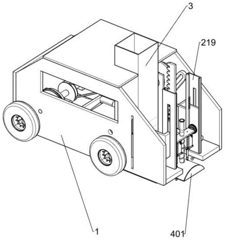
[0029] A speed bump installation device for road construction, such as Figure 1-5 As shown, it includes a car body 1, a power mechanism, a mounting mechanism and a pushing mechanism. In the middle position of the car body 1, the pushing mechanism is connected with the power mechanism, and the right rear side of the pushing mechanism is connected with the left side of the mounting mechanism.

[0030] Working principle: When preparing to install the deceleration belt, first manually put the deceleration belt to be installed into the pushing mechanism, start the power mechanism, and the power mechanism drives the pushing mechanism to push the deceleration belt into the installation mechanism one by one, and the installation mechanism will The deceleration belt in the mechanism is drilled and installed on the road. When the power mechanism drives the pushing mechanism to push the deceleration belt into the installation device, the power mechanism moves forward with the vehicle bo...

Embodiment 2

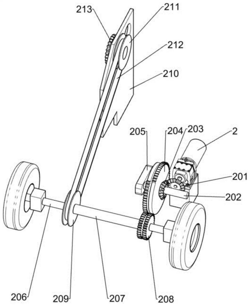
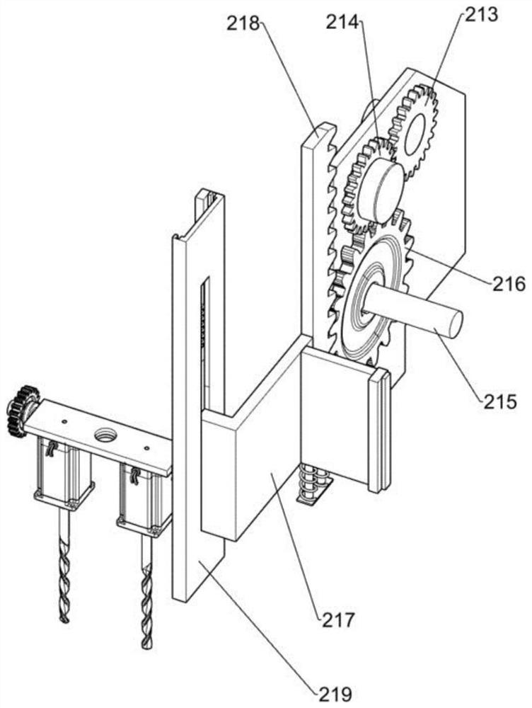
[0032] On the basis of Example 1, such as figure 2 As shown, the power mechanism includes a first motor 2, a first bevel gear 201, a first shaft 202, a second bevel gear 203, a missing tooth gear 204, a fixed frame 205, a second shaft 206, a sleeve 207, a first Straight gear 208, first pulley 209, first fixed plate 210, second pulley 211, belt 212, second spur gear 213, third spur gear 214, third shaft 215 and turntable 303, first motor 2. It is fixedly installed on the left front side inside the car body 1. The first bevel gear 201 is fixedly installed on the left end of the output shaft of the first motor 2. The fixing frame 205 is fixedly installed on the left front side inside the car body 1. The fixing frame 205 is located on the first motor 2, the first shaft 202 is rotatably mounted on the front side of the upper end of the fixed frame 205, and the two toothless gears 204 are fixedly mounted on the rear side of the first shaft 202, and the middle position of the first ...

Embodiment 3

[0039] On the basis of embodiment 1 and embodiment 2, such as Figure 6As shown, a dust suction mechanism is also included. The dust suction mechanism includes a dust washing plate 4, a pressing plate 401, a second sliding column 402 and an elastic member. The dust washing plate 4 is fixedly installed on the front and rear sides of the lower right side of the car body 1 The second sliding column 402 is slidably installed in the middle of the second fixing plate 220, the pressing plate 401 is fixedly installed on the lower end of the second sliding column 402, the elastic member is sleeved on the second sliding column 402, and the elastic member is located between the second fixing plate 220 and the second fixing plate 220. Between the platen 401.

[0040] Working principle: when the carriage 217 moves down with the second fixed plate 220, the dust suction mechanism moves down with the second fixed plate 220, and when the pressure plate 401 is supported on the ground, the secon...


PUM


Abstract

The invention relates to the technical field of traffic deceleration strips, in particular to a deceleration strip mounting device for highway construction. The deceleration strip installation devicefor highway construction has the dust collection function and can achieve automatic feeding and punching. According to the technical scheme, the deceleration strip mounting device for highway construction comprises a vehicle body, a power mechanism, a mounting mechanism and a pushing mechanism. The power mechanism is fixedly installed on one side of the vehicle body, the mounting mechanism is fixedly installed on the side, away from the power mechanism, of the vehicle body, the pushing mechanism is installed in the middle of the vehicle body and connected with the power mechanism, and the other side of the pushing mechanism is connected with the installation mechanism. A first motor is adopted as a source of the whole power mechanism, the power mechanism is connected with the pushing mechanism and the mounting mechanism, a deceleration strip is mounted through cooperation of all the mechanisms, the manual punching and mounting process of workers is replaced, the labor intensity of theworkers is relieved, and physical waste of the workers is reduced.

Description

technical field [0001] The invention relates to the technical field of traffic deceleration belts, in particular to a deceleration belt installation device for road construction. Background technique [0002] In layman's terms, the deceleration belt is the road belt that reduces our speed. At the critical intersection that needs to reduce the speed, it can greatly reduce the speed of the speeding car. The deceleration belt is designed according to the principle of special rubber on the ground. Special rubber tires and when cars cross the road, industrial and mining enterprises, campuses, residential quarters and other imports slow down the speed of motor vehicles. With the development of the economy, more and more vehicles on the road are produced. It is to suppress the occurrence of traffic accidents and ensure the safety of people's lives. Speed ​​bumps can be said to be one of the essential facilities in our traffic. It is of great help to greatly reduce traffic accidents...

Claims


Application Information

Patent Timeline
Patent Type & Authority Applications(China)
IPC IPC(8): E01F9/529B08B15/00
CPCB08B15/00E01F9/529
Inventor 郭立谢
Owner 黑龙江省交通规划设计研究院集团有限公司
Why Eureka
Try Eureka