Marine monitoring structure

A marine and mounting frame technology, applied in the direction of measuring devices, ships, instruments, etc., can solve the problems of poor concealment, high cost, poor economic applicability, etc., and achieve the effect of good concealment and convenient operation

Pending Publication Date: 2021-01-08
XIAMEN UNIV OF TECH
View PDF0 Cites 2 Cited by
  • Summary
  • Abstract
  • Description
  • Claims
  • Application Information

AI Technical Summary

Problems solved by technology

In the existing technology, the solution of directly using the equipped flow rate instrument to measure the flow rate of the surface seawater will lead to high cost, and the simple monitoring is not economical and has poor concealment

Method used


Image

  • Marine monitoring structure
  • Marine monitoring structure
  • Marine monitoring structure

Examples


no. 1 Embodiment approach

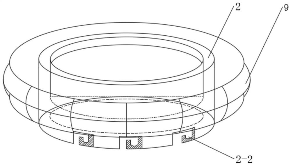
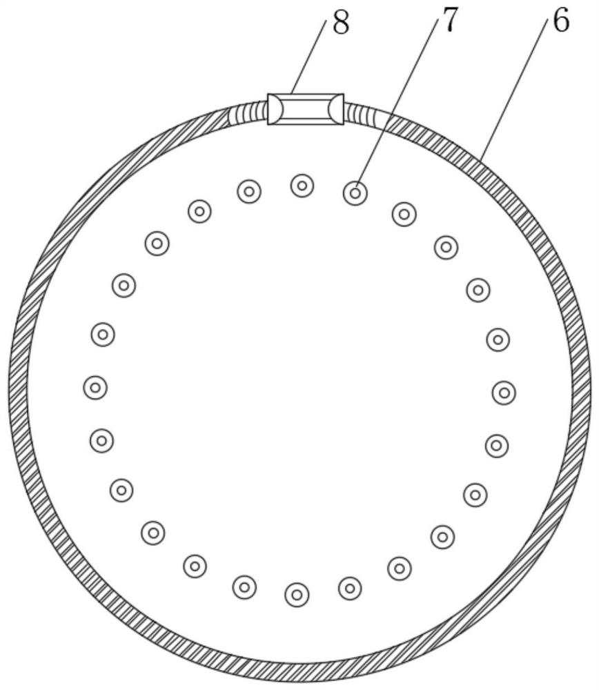
[0035] see Figure 4 , the lighting parts 910 electrically connected to the control modules 1-4 are installed in the lifting assembly 9, the lighting parts 910 are arranged in a plurality of rings at a given interval, and the lighting parts 910 are arranged in the inner cavity of the airbag ring 10; specifically, by The control module 1-4 receives the communication command and controls the opening and closing of the lighting device 910. After the lighting device 910 is turned on, the inner cavity of the airbag ring 10 is heated and expands, and the volume gradually increases, so that the buoyancy of the overall structure increases, and the monitoring structure rises and submerges gradually. Out of the sea, the inner wall of the airbag ring 10 can be preferably white or other warm colors to speed up the expansion rate of the inner cavity of the airbag ring 10, the heat will be transferred and exhausted through the natural cooling of the airbag ring 10, the volume of the airbag r...

no. 2 Embodiment approach

[0037] see Figure 5 , the lifting assembly 9 is provided with a heating element 920 electrically connected to the control module 1-4 and a memory alloy element 921. The memory alloy element 921 is fixedly connected to the heating element 920. In the inner cavity of the ring 10, the heating element 920 is annular, and the memory alloy element 921 is distributed in the inner cavity of the airbag ring 10; specifically, the control module 1-4 receives the communication command and controls the opening and closing of the heating element 920. After the heating element 920 is turned on , the memory alloy part 921 connected to the heating part 920 gradually heats up, and the memory alloy part 921 with shape memory function is heated and expands naturally, supporting the inner cavity of the airbag ring 10, so that the inner cavity of the airbag ring 10 is squeezed by the memory alloy part 921 As the volume gradually increases, the buoyancy of the overall structure increases, and the mon...

no. 3 Embodiment approach

[0039] see Figure 6 , the lifting assembly 9 is provided with a heating dish 930 electrically connected to the control module 1-4 and a vaporized liquid 931 arranged in the heating dish 930, and the heating dish 930 is arranged in an annular shape and closely attached to the inner bottom wall of the airbag ring 10; Specifically, the control module 1-4 receives communication instructions and controls the opening and closing of the heating dish 930, and the heating dish 930 heats the vaporized liquid 931 in it to raise the temperature. The vaporized liquid 931 can be Freon, ether or pentane liquid with a low boiling point. Any liquid in the airbag ring 10, the vaporized liquid 931 in the inner cavity of the airbag ring 10 is heated and vaporized, and the volume of the inner cavity of the airbag ring 10 gradually increases, so that the buoyancy of the overall structure increases, and the monitoring structure rises and gradually dives out of the sea surface. When the vaporized liq...


PUM


Abstract

The invention relates to a marine monitoring structure. The marine monitoring structure comprises a cage frame; the marine monitoring structure further comprises a mounting box and a mounting frame; atemperature sensor is mounted at the bottom end of the mounting frame; the mounting box is arranged above the mounting frame; the cage frame is detachably connected to the bottom of the mounting frame; a solar substrate is arranged at the top end of the mounting box; a transparent cover is arranged on the solar substrate; an image pick-up module and an antenna are installed in the transparent cover; a Beidou positioning terminal, a control module and a power source are installed in an inner cavity of the mounting box; the cage frame comprises a rope and a fish inlet; the two ends of the ropeare fixedly connected with hanging rings; the bottom of the cage frame is fixedly connected with a ring; fishing space is formed among the mounting frame, the cage frame and the ring; and through holes are formed in a fishing nets in the ring. Data of a tidal current surface layer are measured through components on the upper layer, an efficient fishing space can be provided, the economic applicability of the monitoring structure is enhanced, and the cost of the monitoring structure is low.

Description

technical field [0001] The invention relates to the technical field of marine environment monitoring, in particular to a marine monitoring structure. Background technique [0002] With the rapid development of society, maritime trade is becoming more and more prosperous, and there are more and more ships at sea, and the required auxiliary facilities are also diversified. Monitoring equipment can provide people with marine data through supporting facilities and serve marine climate research. , marine environment monitoring, marine ecological restoration, marine resource detection, marine ranching and other fields, to help people make reasonable judgments based on the actual situation of the ocean. In the prior art, the solution of directly using the equipped flow rate instrument to measure the velocity of the surface seawater will lead to high cost, and the simple monitoring is not economical and has poor concealment. Contents of the invention [0003] In order to solve th...

Claims


Application Information

Patent Timeline
Patent Type & Authority Applications(China)
IPC IPC(8): G01D21/02B63B35/00A01K69/08
CPCA01K69/08B63B35/00G01D21/02
Inventor 刘必劲王宇欣
Owner XIAMEN UNIV OF TECH
Why Eureka
Try Eureka